Featured Post Today
print this page

Description. The circuit shown here is of a simple 0 to 9 display that can be employed in a lot of applications. The circuit is based on asynchron...

Read more »

Circuit Diagram Description It’s entirely logical that low-cost miniature microcontrollers have fewer ‘legs’ than their bigger brothers and sis...

Read more »

Description   This device was designed on request; to control the light intensity of four filament lamps (i.e. a ring illuminator) power...

Read more »

Description  Most homes today have at least a few infrared remote controls, whether they be for the television, the video recorder, the stere...

Read more »

Description  The monostable flip flop, sometimes called a 'one shot' is used to produce a single pulse each time it is triggered. It can be u...

Read more »

Description  Commercially available hearing aids are quite costly. Here is an inexpensive hearing aid circuit that uses just four transistors...

Read more »

Description  In most countries it is now mandatory or at least recommended to have a rear fog light on a trailer with the additional requirem...

Read more »
Latest Post
Minimalist Oscilloscope

Minimalist Oscilloscope

Circuit diagram:  Description If you are the proud owner of an old oscilloscope tube, you may be interested in using it once more for its original purpose. All you need are the right voltages on the right pins: in practice you may need to peer closely inside to find out which pins on
0 comments
Fuse Monitor Circuit Diagram

Fuse Monitor Circuit Diagram

This circuit monitors a DC fuse. Its LED lights continously when the fuse is intact but blinks is the fuse is broken. The fuse monitor circuit is designed for 12 volts but can be modified for other voltages. To use this circuit for 6 volts, divide all resistance values by two, for 24 volts, d
0 comments
High Quality Intercom Circuit Diagram

High Quality Intercom Circuit Diagram

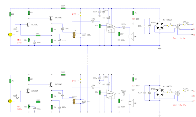
Description: A very high quality intercom, which may also be used for room monitoring. Circuit diagram Notes: This circuit consists of two identical intercom units. Each unit contains a power supply, microphone preamplifier, audio amplifier and a Push To Talk (PTT) relay circuit. Only 2 wire
0 comments
Voltage Doubler Circuit

Voltage Doubler Circuit

Circuit Diagram Schematic Diagram for a Voltage Doubling Circuit (capacitor values are in microF) This is a circuit that outputs a voltage Vout that is approximately twice the level of the Vcc voltage.     The circuit uses a 555 timer IC configured a
1 comments
LED Traffic Lights

LED Traffic Lights

Description   The LED traffic Light circuit controls 6 LEDs (red, yellow and green) for both north/south directions and east/west directions. The timing sequence is generated using a CMOS 4017 decade counter and a 555 timer. Counter outputs 1 through 4 are wire ORed using 4 diodes so
0 comments
Frequency Divider 2  Circuit

Frequency Divider 2 Circuit

Description   This is a classic divider of frequency via two. It is achieved with a classic circuit T-flipFlop, round IC1 [ 4011 ]. In the circuit, the frequency of network, after are limit the negative half-s period of sine wave and transform in square wave, are divided via two. Thu
0 comments
Automatic Loudness Control

Automatic Loudness Control

Circuit diagram: Parts P1 10K Linear Potentiometer (Dual-gang for stereo) R1,R6,R8 100K 1/4W Resistors R2 27K 1/4W Resistor R3,R5 1K 1/4W Resistors R4 1M 1/4W Resistor R7 20K 1/2W Trimmer Cermet C1 100nF 63V Polyester Capacitor C2 47nF 63V Polyester Capacitor C3 470nF 63V Polyester
0 comments
A Very Useful Timed Beeper Circuit Schematic

A Very Useful Timed Beeper Circuit Schematic

Description  This circuit is intended for alerting purposes after a certain time is elapsed. It is suitable for table games requiring a fixed time to answer a question, or to move a piece etc. In this view it is a modern substitute for the old sandglass. Useful also for time control when
0 comments
Speech Filter

Speech Filter

Description  The human speech apprehend a small area of frequencies, that is extended from 300HZ until 3KHZ. This spectrum is also internationally recognized for the transmission of speech via telecommunications networks. This is also the mainer use of this circuit, one and it can be used
1 comments
 QRP antenna tuner circuit

QRP antenna tuner circuit

Description. Low power ( 3 to 30 MHz)  transmitters constructed by hams are generally called QRP’s. For such transmitters a well tuned antenna is a must.If the impedance is not properly matched there will be a little or no output.But if properly matched there will be great results.A cir
0 comments
Zero degree Celsius alarm

Zero degree Celsius alarm

Description. This simple circuit will produce an alarm whenever the temperature falls below zero degree. A thermistor is used here to sense temperature. The op-amp LM7215 is used to compare the reference voltage and voltage from the thermistor network. Reference voltage is given to the non i
0 comments
Automatic Windshield Washer Control

Automatic Windshield Washer Control

Description  Most, if not all, recent cars have an impressive amount of electronics, whether it be ABS brake systems, engine control with injection calculators, airbag activation, or other various functions, called comfort functions. Among them is one which we tend to forget because it h
1 comments
Mini High-Voltage Generator

Mini High-Voltage Generator

Circuit diagram: Description  Here’s a project that could be useful this summer on the beach, to stop anyone touching your things left on your beach towel while you’ve gone swimming; you might equally well use it at the office or workshop when you go back to work. In a very small spac
1 comments
3W FM Transmitter Circuit Diagram

3W FM Transmitter Circuit Diagram

Description This is the schematic for an FM transmitter with 3 to 3.5 W output power that can be used between 90 and 110 MHz. Although the stability isn't so bad, a PLL can be used on this circuit. This is a circuit that I've build a few years ago for a friend, who used it in combination wit
0 comments
XTal Tester

XTal Tester

Circuit diagram  This is a simple XTal tester circuit. T1 and XTal have formed an oscillator. C1 and C2 are voltage divider for oscillator. if the XTal is safe, the oscillator will work well and its output voltage will be rectified by C3, C4, D1 and D2, then T2 will run and LED will lig
0 comments
Emergency Light & Alarm

Emergency Light & Alarm

Powered by two AA NI-CD batteries Four switchable options Circuit diagram Parts: R1 220K 1/4W Resistor R2 470R 1/2W Resistor R3 390R 1/4W Resistor R4 1K5 1/4W Resistor R5 1R 1/4W Resistor R6 10K 1/4W Resistor R7 330K 1/4W Resistor R8 470R 1/4W Resistor R9 100R 1/4W Res
0 comments
Running Message Display LED Circuit

Running Message Display LED Circuit

Description Light emitting diodes are advan- tageous due to their smaller size, low current consumption and catchy colours they emit. Here is a running message display circuit wherein the letters formed by LED arrangement light up progressively. Once all the letters of the message have been
1 comments
Circuit Project: 12V Touch Switch Exciter

Circuit Project: 12V Touch Switch Exciter

This circuit is designed to generate a 20KHz pseudo sine wave signal that can power about 50 remote touch activated switch circuits.  It can support a cable length of about 2500 feet.  A typical remote switch circuit is also shown as well as a receiver circuit for those switches. Ci
0 comments
Temperature-Controlled Soldering Iron

Temperature-Controlled Soldering Iron

Description One reason why commercial soldering stations are expensive is that, in general, they require the use of soldering irons with inbuilt temperature sensors, such as thermocouples. This circuit eliminates the need for a special sensor because it senses the temperature of a solderin
0 comments
AC 220 Volts Flashing Lamps Circuit

AC 220 Volts Flashing Lamps Circuit

Circuit diagram  This circuit is intended as a reliable replacement to thermally-activated switches used for Christmas tree lamp-flashing. The device formed by Q1, Q2 and related resistors triggers the SCR. Timing is provided by R1, R2 & C1. To change flashing frequency do not mo
0 comments
Dark Activated Led or Lamp Flasher

Dark Activated Led or Lamp Flasher

Description  This circuit adopts the rather unusual Bowes/White emitter coupled multivibrator circuit. The oscillation frequency is about 1Hz and is set by C1 value. The LED starts flashing when the photo resistor is scarcely illuminated. The onset of flashing can be set by trimming R2.&n
0 comments
Electronic Selector for 8 Sources

Electronic Selector for 8 Sources

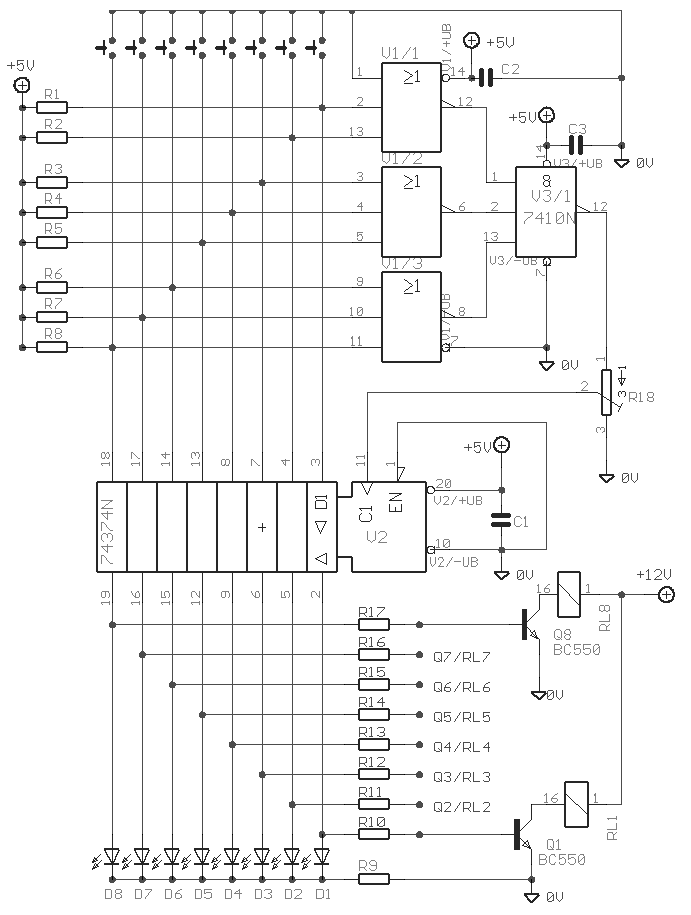
Description   The Elect. Sel. 8 is a simple circuit, with a choice of 8 sources of any sort ,of 8 independent switches. Each switch corresponding with a relay for example the switch S1 activates the RL1 e.t.c. The uses of the circuit are quite a few, choice of entrances in a sound am
0 comments
1000Watt Audio Power Amplifier Blazer Circuit

1000Watt Audio Power Amplifier Blazer Circuit

1000Watt Audio Power Amplifier Blazer Circuit This is a audio power amplifier Blazer circuit provides up to 1000Watt . This fascinating routes several sensible bass and treble alive.  Importantly ought to opt for Power offer supply, that has been fairly high voltage category 70Vdc GN
0 comments
Connection Tester Circuit Diagram

Connection Tester Circuit Diagram

Description:   A low resistance ( 0.25 - 4 ohm) continuity tester for checking soldered joints and connections. Circuit diagram  Notes:  This simple circuit uses a 741 op-amp in differential mode as a continuity tester. The voltage difference between the non-inverting an
0 comments
Precision Audio Millivoltmeter

Precision Audio Millivoltmeter

Measures 10mV to 50Volt RMS in eight ranges Simply connect to your Avo-meter set @ 50uA range Circuit diagram Parts: R1 909K 1/2Watt 1% Metal Oxide Resistor R2 90K9 1/2Watt 1% Metal Oxide Resistor R3 9K09 1/2Watt 1% Metal Oxide Resistor R4 1K01 1/2Watt 1% Metal Oxide Resistor R5 100K 1/4
0 comments
 Photocell based night light

Photocell based night light

Description. Many automatic night light circuits had been published here. This one uses a photocell for detecting the light intensity. At full light the resistance of the photocell will be few ten ohms and at darkness it will rise to several hundred ohms. The IC1 uA741 is wired as a comparato
0 comments
 Proximity detector circuit

Proximity detector circuit

NE567  tone decoder / PLL IC. NE567 is a tone decoder IC from Philips. The IC has a built in PLL circuit with AM lock detection and an output driver circuit. The main function of NE567 is to drive a load (usually LED) when a frequency with in its detection band is available at the IC’s
0 comments
Voltage follower with 1G ohm input resistance

Voltage follower with 1G ohm input resistance

Circuit diagram  This circuit uses an LM11 to form a voltage follower with 1G ohm input resistance built using standard resistor values. With the input disconnected, the input offset voltage is multiplied by the same factor as R2; but the added error is small because the offset voltage
0 comments
Transmitter FM 45W with valve

Transmitter FM 45W with valve

TECHNICAL CHARACTERISTICS:  Tendency of catering: 220V AC Frequency of emission at FM: 88~108MHz Force of expense: max 45W (without the R3)  Circuit diagram Materially:  R1 15KW/2W R2 1KW/10W R3 1KW/10W (for biggest force in the exit you replace with short-circuit). C1
0 comments
Simple Touch Switch Circuit

Simple Touch Switch Circuit

Description Similar to the CMOS based Touch Switch also on this site, this transistor based touch switch can activate a load simply by the user touching a metal plate. It is designed to directly switch a relay to allow it to be used with large loads. As it uses only a few commonly available
0 comments
Police siren using NE555

Police siren using NE555

Description. A lot of electronic circuits using NE555 timer IC are already published here and this is just another one.Here is the circuit diagram of a police siren based on NE55 timer IC. The circuit uses two NE555 timers ICs and each of them are wired as astable multivibrators.The circuit c
0 comments
 Remote Control Circuit Through RF Without Microcontroller

Remote Control Circuit Through RF Without Microcontroller

Description  This is a simple type remote control by using RF communication without microcontroller. In this project a remote has been designed for various home appliances like television, fan, lights, etc. It gives lot of comfort to the user since we can operate it by staying at one plac
0 comments
Pages (26)1234567 Next
 
Support : Creating Website | Johny Template | Mas Template
Copyright © 2011. The Circuit - All Rights Reserved
Template Created by Creating Website Published by Mas Template
Proudly powered by Blogger