Featured Post Today
print this page
Latest Post
Showing posts with label audio amplifier circuit. Show all posts

A Hiqh Quality Headphone Amplifier Circuit

Description
Some lovers of High Fidelity headphone listening prefer the use of battery powered headphone amplifiers, not only for portable units but also for home “table” applications. This design is intended to fulfill their needs. An improved output driving capability is gained by making this a push-pull Class-B arrangement. Output power can reach 100mW RMS into a 16 Ohm load at 6V supply with low standing and mean current consumption, allowing long battery duration.
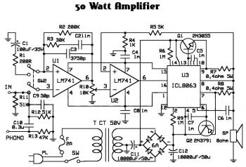
Circuit Diagram
Parts
  • P1 = 22K Potentiometer
  • R1 = 15K Resistor
  • R2 = 100K Resistor
  • R3 = 100K Resistor
  • R4 = 47K Resistor
  • R5 = 470R Resistor
  • R6 = 500R Resistor
  • R7 = 1K Resistor
  • R8 = 18K Resistor
  • R9 = 18K Resistor
  • R10 = 2.2R Resistor
  • R11 = 2.2R Resistor
  • R12 = 33R Resistor
  • R13 = 4.7K Resistor
  • C1 = 10uF-25V Capacitors
  • C2 = 10uF-25V Capacitors
  • C3 = 100nF-63V (PF)
  • C4 = 220uF-25V Capacitors
  • C5 = 100nF-63V (PF)
  • C6 = 220uF-25V Capacitors
  • Q1 = BC560C PNP Transistor
  • Q2 = BC560C PNP Transistor
  • Q3 = BC550C NPN Transistor
  • Q4 = BC550C NPN Transistor
  • Q5 = BC560C PNP Transistor
  • Q6 = BC327 PNP Transistor
  • Q7 = BC337 NPN Transistor
  • J1 = RCA Audio Input Socket
  • J2 = 3mm Stereo Jack Socket
  • B1 = 6V Battery Rechargeable
  • SW1=SPST Slide or Toggle Switch

Notes:
  • For a Stereo version of this circuit, all parts must be doubled except P1, SW1, J2 and B1.
  • Before setting quiescent current rotate the volume control P1 to the minimum, Trimmer R6 to maximum resistance and Trimmer R3 to about the middle of its travel.
  • Connect a suitable headphone set or, better, a 33 Ohm 1/2W resistor to the amplifier output.
  • Switch on the supply and measure the battery voltage with a Multimeter set to about 10Vdc fsd.
  • Connect the Multimeter across the positive end of C4 and the negative ground.
  • Rotate R3 in order to read on the Multimeter display exactly half of the battery voltage previously measured.
  • Switch off the supply, disconnect the Multimeter and reconnect it, set to measure about 10mA fsd, in series to the positive supply of the amplifier.
  • Switch on the supply and rotate R6 slowly until a reading of about 3mA is displayed.
  • Check again the voltage at the positive end of C4 and readjust R3 if necessary.
  • Wait about 15 minutes, watch if the current is varying and readjust if necessary.
  • Those lucky enough to reach an oscilloscope and a 1 KHz sine wave generator can drive the amplifier to the maximum output power and adjust R3 in order to obtain a symmetrical clipping of the sine wave displayed.
Technical data:
Output power (1 KHz sine wave):
  • 16 Ohm: 100mW RMS
  • 32 Ohm: 60mW RMS
  • 64 Ohm: 35mW RMS
  • 100 Ohm: 22.5mW RMS
  • 300 Ohm: 8.5mW RMS
Sensitivity:
  • 160mV input for 1V RMS output into 32 Ohm load (31mW)
  • 200mV input for 1.27V RMS output into 32 Ohm load (50mW)
Frequency response at 1V RMS:
  • Flat from 45Hz to 20 KHz, -1dB at 35Hz, -2dB at 24Hz
Total harmonic distortion into 16 Ohm load at 1 KHz:
  • 1V RMS (62mW) 0.015% 1.27V RMS (onset of clipping, 100mW) 0.04%
Total harmonic distortion into 16 Ohm load at 10 KHz:
  • 1V RMS (62mW) 0.05% 1.27V RMS (onset of clipping, 100mW) 0.1%
  • Unconditionally stable on capacitive load
 Source: http://www.redcircuits.com
0 comments

Improved 3 Transistor Audio Amp (80 milliwatt) Circuit

Description
This circuit is similar to the 3 Transistor Audio Amp but uses positive feedback to get a little more amplitude to the speaker. I copied it from a small 5 transistor radio that uses a 25 ohm speaker. In the circuit above, the load resistor for the driver transistor is tied directly to the + supply. This has a disadvantage in that as the output moves positive, the drop across the 470 ohm resistor decreases which reduces the base current to the top NPN transistor. Thus the output cannot move all the way to the + supply because there wouldn't be any voltage across the 470 resistor and no base current to the NPN transistor.
This circuit corrects the problem somewhat and allows a larger voltage swing and probably more output power, but I don't know how much without doing a lot of testing. The output still won't move more than a couple volts using small transistors since the peak current won't be more than 100mA or so into a 25 ohm load. But it's an improvement over the other circuit above.
In this circuit, the 1K load resistor is tied to the speaker so that as the output moves negative, the voltage on the 1K resistor is reduced, which aids in turning off the top NPN transistor. When the output moves positive, the charge on the 470uF capacitor aids in turning on the top NPN transistor.
The original circuit in the radio used a 300 ohm resistor where the 2 diodes are shown but I changed the resistor to 2 diodes so the amp would operate on lower voltages with less distortion. The transistors shown 2n3053 and 2n2905 are just parts I used for the other circuit above and could be smaller types. Most any small transistors can be used, but they should be capable of 100mA or more current. A 2N3904 or 2N3906 are probably a little small, but would work at low volume.
The 2 diodes generate a fairly constant bias voltage as the battery drains and reduces crossover distortion. But you should take care to insure the idle current is around 10 to 20 milliamps with no signal and the output transistors do not get hot under load.
The circuit should work with a regular 8 ohm speaker, but the output power may be somewhat less. To optimize the operation, select a resistor where the 100K is shown to set the output voltage at 1/2 the supply voltage (4.5 volts). This resistor might be anything from 50K to 700K depending on the gain of the transistor used where the 3904 is shown
Circuit Diagram

0 comments

Audio Amplifier with High Clarity Circuit Diagram

Circuit Diagram
Description
The heart of the circuit is TDA7294 which acts as an amplifier the right and left input feded from the pre amplifier circuit is amplified after passing through the noise filter which contains an RC circuit, the volume is controlled by the variable resistor 47k. and the automatic gain control is provided by the operational amplifier circuit opp amp IC249 For both right channel and left channel., the speaker used is an 8 ohms 40 watts speaker. 

0 comments

Power Amplifier Circuit Diagram with 2n3055

Circuit Diagram
Description
Simple and low cost. The optimal accumulation voltage is about 50V, but this amp assignment from 30 to 60V. The acute ascribe voltage is about 0.8 – 1V. As you can see, in this architecture the apparatus accept a big tolerance, so you can body it about of the components, which you acquisition at home. The and transistors can be any NPN blazon ability transistor, but do not use Darlington types… The achievement ability is about 60W.
Descriptions:
- capacitor C1 regulates the low frequencies (bass), as the capacitance grows, the low frequncies are accepting louder.
- capacitor C2 regulates the college frequencies (treble), as the capacitance grows, the college frequencies are accepting quiter.
- this is a chic B amplifier, this means, that a accepted charge breeze through the end transistors, alike if there is no arresting on the input. This accepted can be adapted with the 500Ω trimmer resistor. As this accepted incrases, the complete of the amplifier gets better, but the end transistors are added heating. But if this accepted decrases, the transistors are not heating so much, but the complete gets worse…

0 comments

300W Subwoofer Amplifier Circuit Diagram

Description
This is an amplifier circuit that is formed from a transistor amplifier miraculous. This circuit is used in the speaker subwoofer with 300W maximum power on each side. To apply it, can be used in the room that is not too large, like the car. And the voltage needed between 25 to 42 Volt DC.
Circuit Diagram 
0 comments

High Power Audio Amplifier 2800W Circuit Schematic Diagram

Description
Mono high power amplifier is actually a powerful 1400 W, but if this hihgh power amplifier circuit is doubled and you want to create stereo, high power amplifier the necessary components and pcb requires two-fold. So if the stereo high power amplifier 2 X 1400W. Schematic Circuit diagram is still less by looking at the circuit that was so below, the finished circuit has been added with a gains using JRC4558 IC by the two and the picture ic where it can be seen below. For circuit buffers, drivers, and booster use multiple transistors and other components (can be seen listed component). And high power amplifier project that is so below is just part of the buffer and driver while the booster has not been made​​. For additional transistors in the booster or high power amplifier end scheme can be found Booster output power amplifier.
Circuit Schematic Diagram :
Part List :
R1_____560Ω
R2_____100Ω
R3_____2K2Ω
R4_____560Ω
R5_____1Ω
R6_____27KΩ
R7_____10KΩ
R8_____100Ω
R9_____100Ω
R10____100Ω
R11____12KΩ
R12____100Ω
R13____100Ω
R14____100Ω
R15____27KΩ
R16____2K2Ω
R17____560Ω
R18____100Ω
R19____10KΩ
R20____330Ω
R21____47Ω 2W
R22____56Ω
R23____2K2Ω
R24____22Ω
R25____56Ω
R26____180Ω
R27____500-1KΩ Trim
R28____560Ω
R29____56Ω
R30____56Ω
R31____22Ω 1W
R32____5Ω6 2W
R33____10Ω
R34____180Ω
R35____100Ω
R36____22Ω 2W
R37____180Ω
R38____56Ω
R39____47Ω 2W
R40____5Ω6 2W
R41____10Ω
R42____10Ω
R43____10Ω
R45____10Ω
R46____0.22Ω 5W
R47____0.22Ω 5W
R48____0.22Ω 5W
R49____0.22Ω 5W
R50____10Ω 5W
C1_____1цF
C2_____1.5nF
C3_____0.1цF 250-275V
C4_____0.1цF 250-275VC5_____100nF
C6_____100цF 50V
C7_____39pF
C8_____330pF
C9_____330pF
C10____330pF
C11____47nF 250-275V
C12____220nF 250-275V
T1_____MJE340
T2_____2N5551 / C2240
T3_____2N5551 / C2240
T4_____2N5551 / C2240
T5_____2N5551 / C2240
T6_____2N5401 / BF423
T7_____2N5401 / BF423
T8_____2N5401 / BF423
T9_____2N5401 / BF423
T10____MJE350
T11____B1186
T12____TIP127
T13____D1763
T14____D1763
T15____B1186
T16____C5198
T17____A1941
T18____2SC2922 / MJ15024G
T19____2SC2922 / MJ15024G
T20____2SA1216 / MJ15025G
T21____2SA1216 / MJ15025G
 This installation include gain JRC4558
This is pcb design
 Installation with booster
 PCB design by SIGMA-4 Madiun ©
0 comments

Simple LM386 Audio Amplifier Circuit Diagram

Description
This simple amplifier shows the LM386 in a high-gain configuration (A = 200). For a maximum gain of only 20, leave out the 10 uF connected from pin 1 to pin 8. Maximum gains between 20 and 200 may be realized by adding a selected resistor in series with the same 10 uF capacitor. The 10k potentiometer will give the amplifier a variable gain from zero up to the maximum.
Circuit Diagram

0 comments

1000Watt Audio Power Amplifier Blazer Circuit

1000Watt Audio Power Amplifier Blazer Circuit
This is a audio power amplifier Blazer circuit provides up to 1000Watt . This fascinating routes several sensible bass and treble alive.
 Importantly ought to opt for Power offer supply, that has been fairly high voltage category 70Vdc GND -70V 10A is that the current low level.

The transistors are 2SC3858 (NPN) and 2SA1494 (PNP), and have high bandwidth, wonderful safe operating space, high linearity and high gain. Driver transistors are 2SC5200 (NPN) and 2SA1943 (PNP). All devices are rated at 230V, with the facility transistors having a 150W dissipation and also the drivers are 50W.

This circuit describes an amplifier, power offer and tests procedures that are all inherently dangerous. Nothing described during this article ought to even be thought-about unless you're totally experienced, grasp specifically what you're doing, and are willing to require full 100% responsibility for what you are doing. There are aspects of the look which will need analysis, fault-finding and/or modification.


0 comments

60 Watt Audio Power Amplifier Circuit Diagram

Description 
To celebrate the hundredth design posted to this website, and to fulfil the requests of many correspondents wanting an amplifier more powerful than the 25W MosFet, a 60 - 90W High Quality power amplifier design is presented here. Circuit topology is about the same of the above mentioned amplifier, but the extremely rugged IRFP240 and IRFP9240 MosFet devices are used as the output pair, and well renowned high voltage Motorola's transistors are employed in the preceding stages.
The supply rails voltage was kept prudentially at the rather low value of + and - 40V. For those wishing to experiment, the supply rails voltage could be raised to + and - 50V maximum, allowing the amplifier to approach the 100W into 8 Ohm target: enjoy! A matching, discrete components, Modular Preamplifier design is available here: Modular Audio Preamplifier.
Amplifier section:
Parts: 

  • R1______________47K 1/4W Resistor
  • R2_______________4K7 1/4W Resistor
  • R3______________22K 1/4W Resistor
  • R4_______________1K 1/4W Resistor
  • R5,R12,R13_____330R 1/4W Resistors
  • R6_______________1K5 1/4W Resistor
  • R7______________15K 1/4W Resistor
  • R8______________33K 1/4W Resistor
  • R9_____________150K 1/4W Resistor
  • R10____________500R 1/2W Trimmer Cermet
  • R11_____________39R 1/4W Resistor
  • R14,R15_________R33 2.5W Resistors
  • R16_____________10R 2.5W Resistor
  • R17_____________R22 5W Resistor (wirewound)
  • C1_____________470nF 63V Polyester Capacitor
  • C2_____________470pF 63V Polystyrene or ceramic Capacitor
  • C3______________47µF 63V Electrolytic Capacitor
  • C4,C8,C9,C11___100nF 63V Polyester Capacitors
  • C5______________10pF 63V Polystyrene or ceramic Capacitor
  • C6_______________1µF 63V Polyester Capacitor
  • C7,C10_________100µF 63V Electrolytic Capacitors
  • D1___________1N4002 100V 1A Diode
  • D2_____________5mm. Red LED
  • Q1,Q2,Q4_____MPSA43 200V 500mA NPN Transistors
  • Q3,Q5________BC546 65V 100mA NPN Transistors
  • Q6___________MJE340 200V 500mA NPN Transistor
  • Q7___________MJE350 200V 500mA PNP Transistor
  • Q8___________IRFP240 200V 20A N-Channel Hexfet Transistor
  • Q9___________IRFP9240 200V 12A P-Channel Hexfet Transistor 
Power supply :
Parts:

  • R1_______________3K9 1W Resistor
  • C1,C2_________4700µF 63V Electrolytic Capacitors (See Notes)
  • C3,C4__________100nF 63V Polyester Capacitors
  • D1_____________400V 8A Diode bridge
  • D2_____________5mm. Red LED
  • F1,F2__________4A Fuses with sockets
  • T1_____________230V or 115V Primary, 30+30V Secondary 160VA Mains transformer
  • PL1____________Male Mains plug
  • SW1____________SPST Mains switch 
Notes:

  • In the original circuit, a three-diode string was wired in series to R10. Two of these diodes are now replaced by a red LED in order to achieve improved quiescent current stability over a larger temperature range. Thanks to David Edwards of LedeAudio for this suggestion.
  • A small, U-shaped heatsink must be fitted to Q6 & Q7.
  • Q8 & Q9 must be mounted on large heatsinks.
  • Quiescent current can be measured by means of an Avo-meter wired in series to the positive supply rail and no input signal.
  • Set the Trimmer R10 to its minimum resistance.
  • Power-on the amplifier and adjust R10 to read a current drawing of about 120 - 130mA.
  • Wait about 15 minutes, watch if the current is varying and readjust if necessary.
  • The value suggested for C1 and C2 in the Power Supply Parts List is the minimum required for a mono amplifier. For optimum performance and in stereo configurations, this value should be increased: 10000µF is a good compromise.
  • A correct grounding is very important to eliminate hum and ground loops. Connect to the same point the ground sides of R1, R3, C2, C3 and C4 and the ground input wire. Connect R7 and C7 to C11 to output ground. Then connect separately the input and output grounds to the power supply ground.
Technical data: 

  1. Output power:
  2. 60 Watt RMS @ 8 Ohm (1KHz sinewave) - 90W RMS @ 4 Ohm
  3. Sensitivity:
  4. 1V RMS input for 58W output
  5. Frequency response:
  6. 30Hz to 20KHz -1dB
  7. Total harmonic distortion @ 1KHz:
  8. 1W 0.003% 10W 0.006% 20W 0.01% 40W 0.013% 60W 0.018%
  9. Total harmonic distortion @10KHz:
  10. 1W 0.005% 10W 0.02% 20W 0.03% 40W 0.06% 60W 0.09%
  11. Unconditionally stable on capacitive loads 
 Source http://www.extremecircuits.net/2010/01/60-watt-audio-power-amplifier-circuit.html
0 comments

100W MOSFET power amplifier

A 100W MOSFET power amplifier circuit based on IRFP240 and IRFP9240 MOSFETs is shown here. The amplifier operates from a +45/-45 V DC dual supply and can deliver 100 watt rms into an 8 ohm speaker and 160 watt rms into a 4 ohm speaker. This Hi-Fi amplifier circuit is suitable for a lot applications like general purpose amplifier, guitar amplifier, keyboard amplifier. The amplifier can be also used as a sub woofer amplifier but a subwoofer filter stage has to be added before the input stage. The amplifier has a low distortion of 0.1%, a damping factor greater than 200, input sensitivity of 1.2V and the bandwidth is from 4Hz to 4 KHz
Circuit diagram.
 About the circuit.
Capacitor C8 is the input DC decoupling capacitor which blocks DC voltage if any from the input source. IF unblocked, this DC voltage will alter the bias setting s of the succeeding stages. Resistor R20 limits the input current to Q1 C7 bypasses any high frequency noise from the input. Transistor Q1 and Q2 forms the input differential pair and the constant current source circuit built around Q9 and Q10 sources 1mA. Preset R1 is used for adjusting the voltage at the output of the amplifier. Resistors R3 and R2 sets the gain of the amplifier. The second differential stage is formed by transistors Q3 and Q6 while transistors Q4 and Q5 forms a current mirror which makes the second differential pair to drain an identical current. This is done in order to improve linearity and gain. Power amplification stage based on Q7 and Q8 which operates in the class AB mode. Preset R8 can be used for adjusting the quiescent current of the amplifier. The network comprising of capacitor C3 and resistor R19 improves high frequency stability and prevents the chance of oscillation. F1 and F2 are safety fuses.
Circuit setup.
Set R1 at midpoint before powering up and then adjust it slowly in order to get a minimum voltage (less than 50mV0 at the output. Next step is setting up the quiescent current and keep the preset R8 in minimum resistance and connect a multimeter across points marked X & Y in the circuit diagram. Now adjust R8 so that the multimeter reads 16.5mV which corresponds to 50mA quiescent current.
Notes.
  • Assemble the circuit on a good quality PCB.
  • Use a +45/-45 V DC, 3A dual supply for powering the circuit.
  • Power supply voltage must not exceed +55/-55 V DC.
  • Before connecting the speaker, check the zero signal output voltage of the amplifier and in any case it should not be higher than 50mV. If it is higher than 50mV, check the circuit for any error. Replacing Q1, Q2 with another set could also solve the problem.
  • Fit Q7 and Q8 to a 2°C/W heat sink. Both Q7 and Q8 must be isolated from the heat sink using mica sheets. Heat sink mounting kits for almost all power transistors/ MOSFETs of almost all package styles are readily available in the market.
  • All resistors other than R10, R11 and R19 are 1/4 watt metal film resistors. R10 and R11 are 5W wire wound type while R19 is a 3W wire wound type.
Power supply for the 100W MOSFET power amplifier.

 A basic dual power supply is used for the amplifier circuit. If 6A ampere bridge is not available, then make one using four 6A6 diodes.C10 and C11 are high frequency bypass capacitors. Filter capacitors C8 and C9 must be at least 10000uF, higher the value lesser the ripple. Optional 3A fuses can be added to the +45 and -45 lines. Transformer T1 can be a 230V primary, 35-0-35 V secondary, 300VA step down transformer.

2 comments

2 Watt Audio Amplifier

Designed for self-powered 8, 4 & 2 Ohm loudspeakers, Bass-boost switch

This amplifier was designed to be self-contained in a small loudspeaker box. It can be feed by Walkman, Mini-Disc, iPod and CD players, computers and similar devices fitted with line or headphone output. Of course, in most cases you will have to make two boxes to obtain stereo.
  
Circuit Diagram:

Parts:

P1 = 10K
R1 = 33K
R2 = 33K
R3 = 33R
R4 = 15K
R5 = 1K
R6 = 1K
R7 = 680R
R8 = 120R-1/2W
R9 = 100R-1/2W Trimmer Cermet
C1 = 10µF-63V
C2 = 10µF-63V
C3 = 100µF-25V
C4 = 470µF-25V
C5 = 47pF-63V
C7 = 470µF-25V
C6 = 220nF-63V
C8 = 1000µF-25V
D1 = 1N4148
Q1 = BC560C
Q2 = BC337
Q3 = TIP31A
Q4 = TIP32A
SW1 = SPST switch
SPKR = 3-5 Watt Loudspeaker

Circuit Operation:

The circuit was deliberately designed using no ICs and in a rather old-fashioned manner in order to obtain good harmonic distortion behavior and to avoid hard to find components. The amplifier(s) can be conveniently supplied by a 12V wall plug-in adapter. Closing SW1 a bass-boost is provided but, at the same time, volume control must be increased to compensate for power loss at higher frequencies. In use, R9 should be carefully adjusted to provide minimal audible signal cross-over distortion consistent with minimal measured quiescent current consumption; a good compromise is to set the quiescent current at about 10-15 mA. To measure this current, wire a DC current meter temporarily in series with the collector of Q3.

Source  http://www.extremecircuits.net
0 comments

600W Audio Amplifier Circuit with +85V 8Ohms

Welcome to free circuit dot com,today We have a circuit for audio amplifier.
We found the circuit in my electronic book,This amplifier power spec is 600W with stereo system.
I’m say a fantatic audio amplifier circuit with completely sound and popular using.
This circuit take high quality electronic components with pair power amp good function and PCB has not bug.
Managing heat of transistor power with light heatsink that guarantee is not over heat.
 Teacnical information
1.Input section responsibility =1.43 RMS
2.Power of amplifier = 600+600W at 85Volt
3.Input Impedance 85000 ohms.
4.THD less than 0.008% at 20 Watts 1000Hz
5.Frequency responsibility 0.3dB at 20Hz and 20KHz
6.Hum and noise less then 177dB 120Hz-20KHz

 Sure!,We have provide schenmetic,PCB and electronic part list for your build it.
 Click On Image And Zoom

And Picture below is electronic part list of this circuit

8 comments

Car Audio Amplifier Circuit Schematic Diagram


Description.

A simple low power car stereo amplifier circuit based on TDA 2003 is shown here. The circuit uses cheap, readily available components and it is very easy to construct. TDA2003 is an integrated car radio amplifier from ST Micro electronics that has a lot of good features like short circuit protection for all pins, thermal over range low harmonic distortion, low cross over distortion etc.
In the circuit given here each TDA2003 is wired as a mono amplifier operating from a 12V supply. Resistors R2 and R3 forms a feedback network that sets the amplifiers gain. C7 is the input DC de-coupling capacitor and C5 couples the speaker to the amplifiers output. C4 is used for improving the ripple rejection while C1 and C2 are employed for power supply filtering. C3 and R1 are used for setting the upper frequency cut-off. Network comprising of C6 and R4 is used for frequency stabilization and to prevent oscillation.

Car audio amplifier Circuit diagram.

Notes.

  • Assemble the circuit on a good quality PCB.
  • Heat sinks are necessary for both ICs.
  • The circuit can be operated from 12V DC.
  • S1 is the ON/OFF switch.
Source http://www.circuitstoday.com
0 comments

2N3055 Power Amplifier

 Simple and low cost. The optimal supply voltage is around 50V, but this amp work from 30 to 60V. The maximal input voltage is around 0.8 - 1V. As you can see, in this design the components have a big tolerance, so you can build it almost of the components, which you find at home. The and transistors can be any NPN type power transistor, but do not use Darlington types... The output power is around 60W.

Some comments:
- capacitor C1 regulates the low frequencies (bass), as the capacitance grows, the low frequncies are getting louder.
- capacitor C2 regulates the higher frequencies (treble), as the capacitance grows, the higher frequencies are getting quiter.
- this is a class B amplifier, this means, that a current must flow through the end transistors, even if there is no signal on the input. This current can be regulated with the 500Ω trimmer resistor. As this current incrases, the sound of the amplifier gets better, but the end transistors are more heating. But if this current decrases, the transistors are not heating so much, but the sound gets worse...
0 comments

600W Audio Amplifier

POWER :
Maximum Output power @ 8ohms : 300watt
Absolute max power supply voltage :±38V to ±40V
Recommended power supply voltage :±30V to ±35V
GENERAL DISCRIPTION :
The circuit is based around {LM4702}manufactured by NATIONAL semiconductors&{MJ11029-MJ11028} by ON semiconductors It is a high fidelity audio power amplifier. Designed for demanding consumer and pro-audio applications. You can also use this circuit with AV receivers, Audiophile power amps, Pro Audio High voltage industrial applications etc Amplifier output power maybe scaled by changing the supply voltage and number of output devices. The circuit includes thermal shutdown circuitry that activates when the die temperature exceeds 150°c. CIRCUIT’s mute function, when activated, mutes the input drive signal and forces the amplifier output to a quiescent state.
0 comments

IC TDA7294 120 Watt Audio Power Amplifier Circuit

 IC TDA7294 120 Watt Audio Power Amplifier Circuit
Amplifer with IC number TDA7293 for process sound system. This amplifer was have the input for a radio, TV, stereo or other line level device. It also has a phono input for a record player, guitar, microphone or other un-amplified source. With the addition of a low pass filter at the input, it makes a great amp for a small subwoofer.
Parts
R : 660 Ohm 1/4 W Resistor = 2 pcs.
R : 22K 1/4 W Resistor = 5 pcs.
R : 10K 1/4 W Resistor = 1 pcs.
R : 30K 1/4 W Resistor = 1 pcs.
C : 2200uF 35V Electrolytic Capacitor = 2 pcs.
C : 0.22uF Capacitor = 2 pcs.
C : 22uF Capacitor = 4 pcs.
C : 0.45uF Capacitor = 2 pcs.
U1,2 : TDA7294 100W DMOS AUDIO AMPLIFIER WITH MUTE/ST-BY
T1 : 50V Center Tapped 5 Amp Transformer
S1 : SPST 3 Amp Switch
S2 : DPDT Switch
F1 : 2 Amp Fuse
SPKR1 : 8 Ohm 120W Speaker
MISC : Case, Knobs, Line Cord, Binding Posts Or Phono Plugs (For Input And Output), Heatsinks For Q1 And Q2
0 comments

200W K1058 J162 MOSFET Class A Audio Amplifier Circuit


J162 K1058 MOSFET amplifier circuit. Welcome to Free dot com circuit we want audio amplifier circuit, as amp is currently composed of two completely separate mono amplifiers for each channel has its own power supply, inter-channel crosstalk zero, a common phenomenon in amplifiers, the same the diet. 40VAC at 640VA to evaluate the performance of a transformer in order to obtain full 40VAC – 0 -.

Unlike many designs that deliver on the capacitors, the current peaks, I prefer the raw power available from the transformer are in rapid transients.

K1058 J162 200 Watts MOSFET amplifier circuit class-A. Although RAS-300 specifications moderate when they hear, immediately causing the huge reserves of power available and not out of fear that something would result in a very strong during the conduct of the amplifier.
2 comments

30 Watt Audio Power Amplifier

 
This project was a sort of challenge: designing an audio amplifier capable of delivering a decent output power with a minimum parts count, without sacrificing quality
The Power Amplifier section employs only three transistors and a handful of resistors and capacitors in a shunt feedback configuration but can deliver more than 18W into 8 Ohm with 0.08% THD @ 1KHz at the onset of clipping (0.04% @ 1W - 1KHz and 0.02% @ 1W - 10KHz) and up to 30W into a 4 Ohm load. To obtain such a performance and to ensure overall stability of this very simple circuitry, a suitable regulated dc power supply is mandatory. This is not a snag because it also helps in keeping noise and hum of the preamp to very low levels and guarantees a predictable output power into different load impedance. Finally, as the amplifier requires only a single rail supply, a very good dc voltage regulator capable of supplying more than 2 Amps @ 40V can be implemented with a few parts
also..... 
Read more at: Link

0 comments

50W Audio Amplifier Circuit

50W Audio Amplifier Circuit
Here the 50W audio amplifier circuit diagram. The amplifier is based ICL8063. This a good amplifier circuit which is easy enough to built.. This circuit can be connected by radio, TV, stereo or other devices.
The circuit is also featured with inputs for the record player, guitar, microphone, and others. If you add low pass filter at the input, it will work like a mini-subwoofer. Circuit scheme presented will guide you in 50W amplifier construction, good luck.
The power supply is splitted type, already added on above circuit diagram.
Components List:
R1 = 200R 1/4W
R2 =200K 1/4W
R3 = 30K 1/4W
R4 = 1K 1/4W
R5 = 5K 1/4W
R6, R9 = 1M 5% 1/2W
R7, R8 = 0,4 ohm 5W
R10 = 10K Pot
R11, R12 = 51K 1/4W
R13 = 47K 1/4W
C4, C6, C5, C7, C8 = 1nF
C9 = 50pF
C10 = 0,3uF
C11, C12 = 10000uF/50V
U1, U2 = IC 741 Op Amp
U3 = ICL8063
Q1 = 2N3055 NPN Power Transistor
Q2 = 2N3791 PNP Power Transistor
D = 250V 6A Bridge Rectifier
T = 50V Center Tapped 5A Tranformer
C1 = 100uF/35V
F1 = 2A Fuse
C2 = 11nF
SPEAKER = 8 ohm 50W
C3 = 3750pF
Heatsinks For Q1 and Q2
50W Audio Amplifier Circuit,
0 comments
 
Support : Creating Website | Johny Template | Mas Template
Copyright © 2011. The Circuit - All Rights Reserved
Template Created by Creating Website Published by Mas Template
Proudly powered by Blogger