Featured Post Today
print this page
Latest Post
Showing posts with label Meter. Show all posts

Decibel Meter Circuit Schematic Diagram

Description
The circuit below responds to sound pressure levels from about 60 to 70 dB. The sound is picked up by an 8 ohm speaker, amplified by a transistor stage and one LM324 op-amp section. You can also use a dynamic microphone but I found the speaker was more sensitive. The remaining 3 sections of the LM324 quad op-amp are used as voltage comparators and drive 3 indicator LEDs or incandescents which are spaced about 3dB apart. An additional transistor is needed for incandescent lights as shown with the lower lamp. I used 12 volt, 50mA lamps. Each light represents about a 3dB change in sound level so that when all 3 lights are on, the sound level is about 4 times greater than the level needed to light one lamp. The sensitivity can be adjusted with the 500K pot so that one lamp comes on with a reference sound level. The other two lamps will then indicate about a 2X and 4X increase in volume.
In operation, with no input, the DC voltage at pins 1,2 and 3 of the op-amp will be about 4 volts, and the voltage on the (+) inputs to the 3 comparators (pins 5,10,12) will be about a half volt less due to the 1N914 diode drop. The voltage on the (-) comparator inputs will be around 5.1 and 6.5 which is set by the 560 and 750 ohm resistors.
When an audio signal is present, the 10uF capacitor connected to the diode will charge toward the peak audio level at the op-amp output at pin 1. As the volume increases, the DC voltage on the capacitor and also (+) comparator inputs will increase and the lamp will turn on when the (+) input goes above the (-) input. As the volume decreases, the capacitor discharges through the parallel 100K resistor and the lamps go out. You can change the response time with a larger or smaller capacitor.
This circuit requires a well filtered power source, it will respond to very small changes in supply voltage, so you probably will need a large filter capacitor connected directly to the 330 ohm resistor. I managed to get it to work with an unregulated wall transformer power source, but I had to use 4700uF. It worked well on a regulated supply with only 1000uF. 
 Circuit Schematic Diagram 1
 Circuit Schematic Diagram 2
0 comments

Digital Volt and Ampere Meter Circuit Diagram

Circuit Diagram 1
Circuit Diagram 2
 Circuit Diagram 3
Description
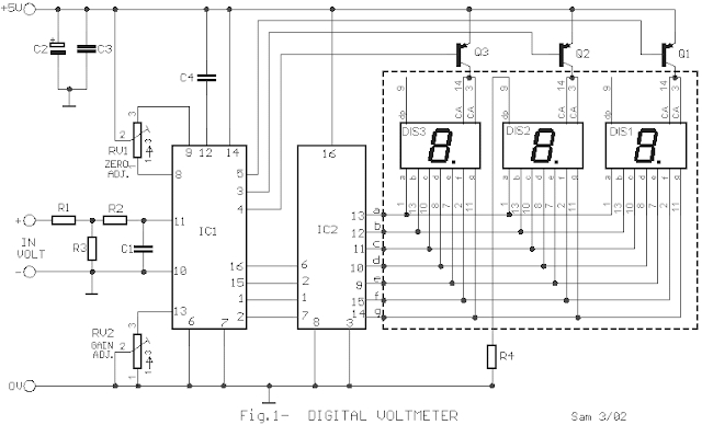
Even if the digital multimeters have dominated in a lot of applications, in the measurement, exist the need for existence of instruments of clue in various appliances, voltage and current, as in power supply or elsewhere. The circuits that give make this precisely the work, measure the voltage in terminal a circuit and the current that passes in his. The circuit does not present particular difficulties for somebody that has a small experience. The two circuits are the himself, with a small difference only in their input, when they have they measure voltage or current and in connection that concern decimal point [ dp ]. In the department of input IC1 and IC3, exist the CA3161E, that is a A/D Converter for 3-Digit Display. In the drive of Display IC2 and IC4, exist CA3161E, that is a BCD the Seven Segment Decoder/ Driver. As it appear in Fig.1, that concern the voltmeter in input [ + IN ], exist in series a what resistor R1 in combination with the R3 create a voltage divider. On the contrary in the Fig.2 that it concern the ampere meter, this resistor does not exist, because the circuit is connected differently, thus the current pass through the R5, creating a fall of voltage, in her terminal, proportional current that it pass from this.
Adjustments

Voltmeter: Short circuit in the input, pins 10 and 11 [IC1] and we regulate the RV1, until we take clue in the Display, zero in all the digits. We rectify and connect in the input a external voltage roughly 900mV. With the RV2, we regulate so that we take the clue 900mV in the Display. At the same time, we check this voltage with a external multimeter, of good quality and precision.

Amperemeter: Short circuit in the input, pins 10 and 11 [IC3] and we regulate the RV4, until we take clue in the Display, zero in all the digits. We rectify and we connect in + IN point, provided that we place in series with the positive pole, of battery, a resistor 10R/10W and in the –IN, a new battery 9V. We regulate the RV3 so that we take clue in the Display 0.90A. We check simultaneously the correctness of measurement with a external digital ambermeter.  A point that it should we are careful, the capacitors C4 and C9, it should they are very good quality. Also the various in the placement of resistors R4 and R7. of connection two circuits, for measurement voltage and current, appear in the Fig.3. The power supply that is public for two circuits appears in the Fig.4. If exist suitable constant supply in the appliance in which will be placed permanently the circuits, then can remove the T1 and bridge GR1 and is connected this voltage, in point A. The IC5 good is placed in heatsink.

Feature
V in maximum: 100V [99.9V]

A in maximum: 10A [9.99A]

Max. measurement Voltage Error: 100mV
Max. measurement Ampere Error: 100mA
Part List
R1=680Kohms C1-5=10nF IC2-4=CA3161E  Intersil-Harris
R2-6=1Mohms C2-6=47uF 16V IC5=7805
R3=6.8Kohms C3-7-10-11=100nF GR1=4X 1N4001
R4-7=270 ohms C4-8=220nF 1% Q1......6=BC557
R5=0.1 ohms 5W C9=2200uF 25V DS1......6= 7Segment Display common anode
RV1-4=50Kohms  trimmer 10 turns C12=10uF 16V T1=230VAC/6VAC 1A
RV2-3=5Kohms trimmer 10 turns IC1-3=CA3162E  Intersil-Harris
Source - http://users.otenet.gr/~%20athsam/digital_volt_and_ambere_meter_eng.htm
2 comments

Digital LED Voltmeter Using ICL7107

Description
This circuit is a circuit diagram? digital voltmeterwith LED display. It’s ideal to use for measuring the output voltage of your DC power supply. It includes a 3.5-digit LED display with a negative voltage indicator. It measures DC voltages from 0 to 199.9V with a resolution of 0.1V. The voltmeter is based on single ICL7107  chip and may be fitted on a small 3cm x 7cm printed circuit board. The circuit should be supplied with a 5V voltage supply and consumes only around 25mA. The use of 7805 5V voltage regulator is highly recommended to prevent the damage of ICL7107, 555 ICs and to extend the operating voltages. The following is a schematic drawing:


Parts list of The Digital LED Voltmeter:
R1 = 8K2 R1 = 8K2
R2 = 47K / 470K R2 = 47k / 470K
R3 = 100K R3 = 100K
R4 = 2K R4 = 2K
R5, R6 = 47K R5, R6 = 47k
R7 = 0R / 4K7 R7 = 0R / 4K7
R8 = 560R R8 = 560R
C1,C5, C6, C8, C9 = 100n C1, C5, C6, C8, C9 = 100n
C2 = 470n / 47n C2 = 470n / 47n
C3 = 220n C3 = 220n
C4 = 100p C4 = 100p
C7 = 10-22u C7 = 10-22U
D1, D2 = 1N4148 D1, D2 = 1N4148
IC1 = ICL7107 IC1 = ICL7107
IC2 = NE555 IC2 = NE555
OPTO = CA 10 pin FTA = CA 10 pin

 Author: anonymous
Source  -http://www.hqew.net/circuit-diagram/Digital-LED-Voltmeter-Using-ICL7107_2848.html
3 comments

Precision Audio Millivoltmeter

Measures 10mV to 50Volt RMS in eight ranges
Simply connect to your Avo-meter set @ 50uA range
Circuit diagram
Parts:
  • R1 909K 1/2Watt 1% Metal Oxide Resistor
  • R2 90K9 1/2Watt 1% Metal Oxide Resistor
  • R3 9K09 1/2Watt 1% Metal Oxide Resistor
  • R4 1K01 1/2Watt 1% Metal Oxide Resistor
  • R5 100K 1/4W Resistor
  • R6 2M2 1/4W Resistor
  • R7 82K 1/4W Resistor
  • R8 12K 1/4W Resistor
  • R9 1K2 1/4W Resistor
  • R10 3K3 1/4W Resistor
  • R11 200R 1/2W Trimmer Cermet
  • C1 330nF 63V Polyester Capacitor
  • C2,C3 100uF 25V Electrolytic Capacitor
  • C4 220uF 25V Electrolytic Capacitor
  • C5 33pF 63V Polystyrene Capacitor
  • C6 2u2 63V Electrolytic Capacitor
  • D1-D4 1N4148 75V 150mA Diodes
  • IC1 CA3140 Op-amp
  • IC2 CA3130 Op-amp
  • SW1 2 poles 5 ways rotary switch
  • SW2 SPDT switch
  • J1 RCA audio input socket
  • J2,J3 4mm. output sockets
  • B1 9V PP3 Battery
  • Clip for PP3 Battery
Notes:
  • Connect J2 and J3 to an Avo-meter set @ 50uA range
  • Switching SW2 the four input ranges can be multiplied by 5
  • Total fsd ranges are: 10mV, 50mV, 100mV, 500mV, 1V, 5V, 10V, 50V
  • Set R11 to read 1V in the 1V range, with a sinewave input of 1V @ 1KHz
  • Compare the reading with that of another known precision Millivoltmeter or with an The oscilloscope reading must be a sinewave of 2.828V peak to peak amplitude
  • Frequency response is flat in the 20Hz-20KHz range
  • If you have difficulties in finding resistor values for R1, R2, R3 & R4, you can use the following trick:
  • R1 = 10M + 1M in parallel
  • R2 = 1M + 100K in parallel
  • R3 = 100K + 10K in parallel
  • R4 = 1K2 + 6K8 in parallel
  • All resistors 1% tolerance 
Author: RED Free Circuit Designs
Source http://www.redcircuits.com/
0 comments

Field-strength meter

Circuit diagram


Original source:

 I saw this circuit in an old issue of "73 Radio Electronics". I built it, but it didn't work well, so I changed a few components to get better sensitivity. 

Description:

This is a very straightforward circuit. The first stage acts as a crystal receiver. Use a germanium detector diode (like 1N34, but AA119 is much more common in Europe), a silicon one won't do. The frequency is determined by L and C. For the FM band and VHF, wind a coil 5mm in diameter, 6-8 turns of coated wire 1mm thick. You can always vary the frequency by spacing the turns a bit looser or tighter. C is much less critical. Something around 100p is preferable, though. The second stage is based around the versatile 2N3819 JFET high-impedance amplifier. With the 470k potentiometer you can adjust sensitivity of the circuit. The trimmer is used to zero the meter. Use any old 50mA or slightly smaller ammeter from the junk box.
  
Problems:
You can't expect great performance from such a simple detector-based meter. Sensitivity is just adequate enough to get a basic idea of the power that your transmitter is capable of. 

Possible uses:
Use the field-strength meter to find out when a transmitter is operating at optimal power. It can be very handy when aligning stages (like in case of the 4W transmitter) or experimenting with different antennas.
0 comments
 
Support : Creating Website | Johny Template | Mas Template
Copyright © 2011. The Circuit - All Rights Reserved
Template Created by Creating Website Published by Mas Template
Proudly powered by Blogger