Featured Post Today
print this page
Latest Post
Showing posts with label radio circuit. Show all posts

2 Transistor FM Voice Transmitter

Warning: Take care with transmitter circuits. It is illegal in most countries to operate radio transmitters without a license. Although only low power this circuit may be tuned to operate over the range 87-108MHz with a range of 20 or 30 metres.
Circuit Diagram 
Notes
  • I have used a pair of BC548 transistors in this circuit. Although not strictly RF transistors, they still give good results. I have used an ECM Mic insert from Maplin Electronics, order code FS43W. It is a two terminal ECM, but ordinary dynamic mic inserts can also be used, simply omit the front 10k resistor. The coil L1 was again from Maplin, part no. UF68Y and consists of 7 turns on a quarter inch plastic former with a tuning slug. The tuning slug is adjusted to tune the transmitter. Actual range on my prototype tuned from 70MHz to around 120MHz. The aerial is a few inches of wire. Lengths of wire greater than 2 feet may damp oscillations and not allow the circuit to work. Although RF circuits are best constructed on a PCB, you can get away with veroboard, keep all leads short, and break tracks at appropriate points.
  • One final point, don't hold the circuit in your hand and try to speak. Body capacitance is equivalent to a 200pF capacitor shunted to earth, damping all oscillations. I have had some first hand experience of this problem.
.
Author: Andy Collinson, anc@mitedu.freeserve.co.uk
Source http://www.zen22142.zen.co.uk/
0 comments

Micro Power AM Receiver Circiut

Circuit Diagram
Description
This is basically a crystal radio with an audio amplifier which is fairly sensitive and receives several strong stations in the Los Angeles area with a minimal 15 foot antenna. Longer antennas will provide a stronger signal but the selectivity will be worse and strong stations may be heard in the background of weaker ones. Using a long wire antenna, the selectivity can be improved by connecting it to one of the taps on the coil instead of the junction of the capacitor and coil. Some connection to ground is required but I found that standing outside on a concrete slab and just allowing the long headphone leads to lay on the concrete was sufficient to listen to the local news station (KNX 1070). The inductor was wound with 200 turns of #28 enameled copper wire on a 7/8 diameter, 4 inch length of PVC pipe, which yields about 220 uH. The inductor was wound with taps every 20 turns so the diode and antenna connections could be selected for best results which turned out to be 60 turns from the antenna end for the diode. The diode should be a germanium (1N34A type) for best results, but silicon diodes will also work if the signal is strong enough. The carrier frequency is removed from the rectified signal at the cathode of the diode by the 300 pF cap and the audio frequency is passed by the 0.1uF capacitor to the non-inverting input of the first op-amp which functions as a high impedance buffer stage. The second op-amp stage increases the voltage level about 50 times and is DC coupled to the first through the 10K resistor. If the pairs of 100K and 1 Meg resistors are not close in value (1%) you may need to either use closer matched values or add a capacitor in series with the 10K resistor to keep the DC voltage at the transistor emitter between 3 and 6 volts. Another approach would be to reduce the overall gain with a smaller feedback resistor (470K). High impedance headphones will probably work best, but walkman stereo type headphones will also work. Circuit draws about 10 mA from a 9 volt source. Germanium diodes (1N34A) types are available from Radio Shack, #276-1123.

0 comments

Long Loopstick Antenna Circuit Diagram

Circuit Diagram 
Description
Wound on a 3 foot length of PVC pipe, the long loopstick antenna was an experiment to try to improve AM radio reception without using a long wire or ground. It works fairly well and greatly improved reception of a weak station 130 miles away. A longer rod antenna will probably work better if space allows. The number of turns of wire needed for the loopstick can be worked out from the single layer, air core inductance formula:
Inductance = (radius^2 * turns^2) / ((9*radius)+(10*length))
where dimensions are in inches and inductance is in microhenrys. The inductance should be about 230 microhenrys to operate with a standard AM radio tuning capacitor (33-330 pF). The 3 foot PVC pipe is wound with approximately 500 evenly spaced turns of #24 copper wire which forms an inductor of about 170 microhenrys, but I ended up with a little more (213uH) because the winding spacing wasn't exactly even. A secondary coil of about 50 turns is wound along the length of the pipe on top of the primary and then connected to 4 turns of wire wound directly around the radio. The windings around the radio are orientated so that the radio's internal antenna rod passes through the external windings. A better method of coupling would be to wind a few turns directly around the internal rod antenna inside the radio itself, but you would have to open the radio to do that. In operation, the antenna should be horizontal to the ground and at right angles to the direction of the radio station of interest. Tune the radio to a weak station so you can hear a definite amount of noise, and then tune the antenna capacitor and rotate the antenna for the best response. The antenna should also be located away from lamp dimmers, computer monitors and other devices that cause electrical interference. 

0 comments

Accurate Bass Tone Control Circuit Diagram

Description
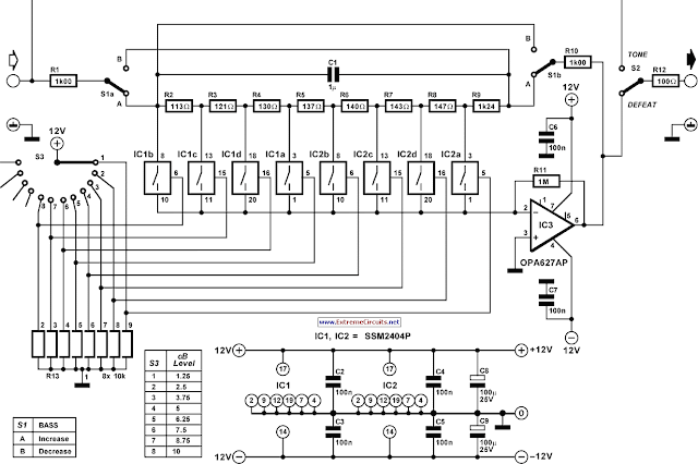
A difficult problem in the design of conventional stereo tone controls is obtaining synchronous travel of the potentiometers. Even a slight error in synchrony can cause phase and amplitude differences between the two channels. Moreover, linear potentiometers are often used in such controls, and these give rise to unequal performance by human hearing. Special potentiometers that counter these difficulties are normally hard to obtain in retail shops. A good alternative is a control based on a rotary switch and a discrete potential divider. The problem with this that for good tone control more than six steps are needed, and switches for this are also not readily available. Fortunately, electronic circuits can remove these difficulties.  
Circuit Diagram:

The analogue selectors used may be driven by mechanical switches, standard logic circuit or a microcontroller. The selectors used in the present circuit are Type SSM2404 versions from Analogue Devices, which switch noiselessly. Each IC contains four selectors, so that a total of eight are used. The step size is 1.25 dB at 20 Hz with a maximum of 10dB . The circuit can be mirrored with S1, which means that a selection may be made of amplification or attenuation of bass frequencies. The user can choose between attenuation only and extending the range by dividing R9. The control can be bridged by switch S2.

To prevent the output impedance of the circuit having too much effect on the operation of the circuit, the output impedance must be ≤ 10 Ω. Resistor R1 2 protects the circuit against too small a load. At maximum bass amplification at Ui n = 1 V r.m.s., the THD+N <0.001% for a frequency range of 20 Hz to 20kHz and and a bandwidth of 80kHz. The circuit draws a current of about 10 mA

0 comments

Simple Op-Amp Radio Circuit Diagram

Circuit Diagram 
Description
This is basically a crystal radio with an audio amplifier which is fairly sensitive and receives several strong stations in the Los Angeles area with a minimal 15 foot antenna. Longer antennas will provide a stronger signal but the selectivity will be worse and strong stations may be heard in the background of weaker ones. Using a long wire antenna, the selectivity can be improved by connecting it to one of the taps on the coil instead of the junction of the capacitor and coil. Some connection to ground is required but I found that standing outside on a concrete slab and just allowing the long headphone leads to lay on the concrete was sufficient to listen to the local news station (KNX 1070). The inductor was wound with 200 turns of #28 enameled copper wire on a 7/8 diameter, 4 inch length of PVC pipe, which yields about 220 uH. The inductor was wound with taps every 20 turns so the diode and antenna connections could be selected for best results which turned out to be 60 turns from the antenna end for the diode. The diode should be a germanium (1N34A type) for best results, but silicon diodes will also work if the signal is strong enough. The carrier frequency is removed from the rectified signal at the cathode of the diode by the 300 pF cap and the audio frequency is passed by the 0.1uF capacitor to the non-inverting input of the first op-amp which functions as a high impedance buffer stage. The second op-amp stage increases the voltage level about 50 times and is DC coupled to the first through the 10K resistor. If the pairs of 100K and 1 Meg resistors are not close in value (1%) you may need to either use closer matched values or add a capacitor in series with the 10K resistor to keep the DC voltage at the transistor emitter between 3 and 6 volts. Another approach would be to reduce the overall gain with a smaller feedback resistor (470K). High impedance headphones will probably work best, but walkman stereo type headphones will also work. Circuit draws about 10 mA from a 9 volt source. Germanium diodes (1N34A) types are available from Radio Shack, #276-1123.

0 comments

Lightning Detector Circuit Diagram

Description
Egor! Come quick! A storm approaches!
Here is a VLF receiver tuned to 300 kHz designed to detect the crackle of approaching lightning. A bright lamp flashes in sychrony with the lightning bolts indicating the proximity and intensity of the storm. Figure 1 shows the simple receiver which consists of a tuned amplifier driving a modified flasher circuit. The flasher is biased to not flash until a burst of RF energy, amplified by the 2N3904, is applied to the base of the 2N4403. The receiver standby current is about 350 microamps which is nothing at all to a couple of D cells, hardly denting the shelf life. Of course, the stormier it gets, the shorter the battery life.
 Circuit Diagram
For best effect, mount the lamp in an old-fashioned holder with an extra-large colored glass lense. Or construct your own fixture with a plate of textured colored glass behind a panel painted with black-crackle paint. Watch a few old science fiction movies for other ideas.
A totally different approach is to mount the circuit in an empty glass jar with the antenna and bulb protruding through the top. (A malted-milk jar has a nice, red plastic lid which is easy to work and looks good.) Use a pin jack for the antenna. The gadget looks quite home-made but fascinating.
Boat owners may wish to replace the lamp with a 3-volt beeper to provide an early warning of approaching bad weather. Choose one of those unbreakable clear plastic jars like the large jars of coffee creamer. A little silicone rubber will seal the antenna hole in the lid of the jar. Use a longer antenna for increased sensitivity since there are few electrical noise sources on the lake.
 Tune-up is simple: adjust the potentiometer until the regular flashing just stops. (Use a multi-turn trimmer.) When properly adjusted, the lamp will occasionally flash when large motors or appliances switch on and off and an approaching storm will give quite a show. Obviously, tune-up is a bit more difficult during stormy weather. Adjust the pot with no antenna if lightning is nearby. Tune an AM radio to the bottom of the dial to monitor the pulses that the lightning detector is receiving.
This lightning detector is not so sensitive that it will flash with every crackle heard on the radio but will only flash when storms are nearby. Increased sensitivity may be achieved by increasing the antenna length. The experienced experimenter may wish to add another gain stage after the first by duplicating the 2N3904 circuitry including capacitor coupling with the addition of a 47 ohm emitter resistor to reduce the gain somewhat. This additional gain can cause stability problems if the layout is poor so novices are advised to use a longer antenna or adjust the sensitivity potentiometer more delicately instead! (When operating properly, the additional gain makes the pot adjustment much less critical.)

8 comments

FM Booster Diagram Circuit

Description
A low-cost circuit of an FM booster that can be used to listen programs from distant FM stations clearly. The circuit comprises a common-emitter tuned RF preamplifier wired around VHF/UHF transistor 2SC2570 ( C2570).
This FM booster circuit is constructed using few common components ( not require some special components ) and provide a very good gain .
To calibrate this circuit you need to adjust input/output trimmers (VC1/VC2) for maximum gain.
Input coil L1 consists of four turns of 20SWG enamelled copper wire (slightly space wound) over 5mm diameter former.
It is tapped at the first turn from ground lead side. Coil L2 is similar to L1, but has only three turns.
Both of the trimmers are 22pF value .This FM radio signal booster needs to be powered by a 12 volts DC power supply .
Circuit Diagram
0 comments

Simple FM Receiver Circuit Diagram

Description
This is the most simple fm receiver with good performances that works great even if the sensitivity is not too high. The working principle of this fm receiver may seem a little unusual. It is made of an oscillator (T2 and T3) that is synchronized with the received frequency of T1.
This transistor works as a broadband preamplifier in VHF range.
 The oscillator is adjusted between 87 … 108 MHz with C5. Because of the synchronization, the oscillator output will have the same frequency deviation as the received signal from the fm antenna. This deviations are caused by the broadcasted audio informations. The frequency modulated signal show up on P1 + R5. Low pass filter R6/C6 extracts the audio signal and then is amplifier by T4 … T6 and transmitted at the output through C9 capacitor.
Circuit Diagram
The coil details are presented in the fm receiver circuit diagram. The radio receiver is adjusted on different stations with the help of C5. P1 potentiometer is adjusted untill the best reception is obtained. If we attach an audio amplifier and a speaker then this fm receiver can be made very compact as a pocket radio.
2 comments

Tuned Radio Frequency (TRF) Receiver Circuit Diagram

Description
Superheterodyne receivers have been mass-produced since around 1924, but for reasons of cost did not become successful until the 1930s. Before the second world war other, simpler receiver technologies such as the TRF receiver and the regenerative receiver were still widespread. The circuit described here is based on the old technology, but brought up-to-date a The most important part of the circuit is the input stage, where positive feedback is used to achieve good sensitivity and selectivity. The first stage is adjusted so that it is not quite at the point of oscillation. This increases the gain and the selectivity, giving a narrow bandwidth.

To achieve this, the potentiometer connected to the drain of the FET must be adjusted very carefully: optimal performance of the receiver depends on its setting. In ideal conditions several strong stations should be obtainable during the day using a 50 cm antenna. At night, several times this number should be obtainable. The frequency range of the receiver runs from 6 MHz to 8 MHz. This range covers the 49 m and the 41 m shortwave bands in which many European stations broadcast. Not bad for such a simple circuit! The circuit employs six transistors. The first stage is a selective amplifier, followed by a transistor detector. Two low-frequency amplifier stages complete the circuit.
Circuit diagram:
The final stage is a push-pull arrangement for optimal drive of the low-impedance loudspeaker. This circuit arrangement is sometimes called a ‘1V2 receiver’ (one preamplifier, one detector and two audio-frequency stages). Setting-up is straightforward. Adjust P1 until the point is reached where the circuit starts to oscillate: a whistle will be heard from the loudspeaker. Now back off the potentiometer until the whistle stops. The receiver can now be tuned to a broadcaster. Occasional further adjustment of the potentiometer may be required after the station is tuned in. The receiver operates from a supply voltage of between 5 V and 12 V and uses very little current. A 9 V PP3 (6F22) battery should give a very long life.
 Author: Gert Baars
0 comments

QRP antenna tuner circuit

Description.
Low power ( 3 to 30 MHz)  transmitters constructed by hams are generally called QRP’s. For such transmitters a well tuned antenna is a must.If the impedance is not properly matched there will be a little or no output.But if properly matched there will be great results.A circuit for matching the antenna properly with the transmitter id given below.
The output of the transmitter is given to the input of the tuner( connector BNC1). The output of the tuner(connector BNC2) must be connected to antenna.Then adjust the L1 and C1 to obtain the maximum transmission power.The transmission power can be checked using a SWR meter.
Circuit diagram with Parts list. 
 

Notes. 
  • Assemble the circuit on a goos quality PCB or common board.
  • If the matching is not satisfactory then change the values of L1,C1,C2&C3  to the next close value and tune again.
  • Proper tuning requires some trial and error.
  • The circuit can be enclosed in an aluminum casing for better performance.
Source -  http://www.circuitstoday.com/qrp-antenna-tuner-circuit
0 comments

Crystal Radio

I have received a number of emails regarding schematics for crystal radios. After about the third email, I figured that I may as well put one on my page. So here it is. The circuit is very simple with only 5 parts, but performs very nicely when used with the right size antenna. 

 Circut  Schematic

Part

Total Qty.

Description

Substitutions
C11Tuning Capacitor (See Notes)
D111N34 Germanium Diode
L11Loopstick Antenna (See Notes)
SPKR11Crystal Earphone
MISC1Wire, Board, Wire For Antenna, Knob For C1
Notes

  1. C1 and L1 can be bought, or salvaged from an old AM radio (which is where I got mine). You may need to experiment with the connections on L1 in order to get the best (or any) signal.
  2. You may or may not need the ground connection. I never use it and the radio usually works fine without it.
  3. The bigger the antenna, the more stations you pick up and the louder you hear them. On my radio, I get about 10 stations, 3 of which are very loud in the earphone. Of course, not everyone has room for a 60' antenna...
  4. A 47K resistor in parallel with the earphone will help properly load the detector (This suggestion from Kb8tej1@aol.com)

 Source http://www.aaroncake.net/circuits/cradio.asp

0 comments

ZN414 Portable AM Receiver

Notes:
Designed around the popular ZN414 ic this receiver covers the AM band from 550 - 1600 KHz with the values shown. For Longwave the coil needs to be changed. Use one from an old MW radio to save time. The ZN414 is a tuned radio frequency designed and incorporates several RF stages and an AM detector. It is easily overloaded and the operating voltage is critical to achieve good results.
The BC107 acts as a voltage follower, the four 1N4148 diodes providing a stable 2.4V supply. With the 10k pot , which acts as a selectivity control, and the b-e voltage drop of the BC107, the operating voltage for the ZN414 is variable from 0 to 1.8volts DC. If you live in an area that is permeated with strong radio signals, then the voltage will need to be decreased. I found optimum performance with a supply of around 1.2 volts. 

 Circuit diagram:

 The audio amplifier is built around an inverting 741 op-amp. Extra current boost is provided using the BC109 / BC179 complementary transistor pair. The voltage gain of the complete audio amplifier is around 15. The audio output of the complete receiver is really quite good and free from distortion. I may provide some sound samples later..


author: Andy Collinson
Source  http://www.zen22142.zen.co.uk/
0 comments

CB receiver

source: Kyriakos Kontakos

Tendency of catering: + 12V DC
Frequency of reception at AM: ~27MHz
 
Materially:
The resistances are 1/4W.

R1, R3, R5
100W
R2
56KW
R4
39KW
R6
560W
R7, R11
6,8KW
R8
220W
R9
2,2KW
R10
5,6KW
R12
10KW logarithmic pontesiometer
R13
1KW
R14
10W
C1
150pF ceramic
C2
39pF ceramic
C3, C5
12pF ceramic
C4
56pF ceramic
C6, C7, C8, C9, C10, C11, C16, C21
47nF ceramic
C12, C19
47mF/16V electrolytic
C13, C14
10nF ceramic
C15
100nF polyester
C17
10mF/16V electrolytic
C18
2,2mF/16V electrolytic
C20
470mF/16V electrolytic
D1
AA119, AA117 (germanium diode)
Q1, Q2
BF241 (amplifiers of intermediary frequency)
U1
SO42P (mixed and local oscillator)
U2
LM386 (amplifier A.F.)
Y1, Y2
Crystals hails. (You can you put the so much, those who also channels that you want you touch). See here.
MF1
Medium frequency 455KHz, core yellow. *
MF2
Medium frequency 455KHz, core white. *
MF3
Medium frequency 455KHz, core black. *
L1, L2
Wires of coper (smaltwme'na) with diameter 0,4mm wrapped in plastic support of diameter 6-7mm of perjstrofjkoy' core. For the L1 you wrap 13 coils. For the L2 you wrap 4 coils.
LS1
Loudspeaker 8W/1W.
ANT1
Aerial for CB (For the trials is enough a piece wire of few metres).
S1
Switch of choice of channel. It has so much places, those who also the channels that you want to touch.
* Intermediary frequencies mf1-3 you can him find in a old radio AM.


Regulations:
For the regulation needs a transmitter or generator in mpa'nta the CB, that is to say in the region 27MHz. If you have a certain friend with CB, you convince you to help.
    1. Connect a piece of cable around in the one metre in the place of aerial.
    2. Be supplied the receptor with + 12V and turn in half the potentiometer of regulation of sound (R12).
    3. Turn on the generator or the transmitter CB and you emit in distance of 10 metres roughly from the receptor, in the channel that receives the receptor..
    4. From the loudspeaker it will be supposed it begins to be heard what you emit and if it does not have big force, you turn the core of inductor L1/L2 until you have a increase of intensity. After this you can continue with the various medium frequencies beginning from black (MF3) until you have the biggest intensity. If it is heard mjkrofwnjsmo's, you lower little the intensity of loudspeaker or you remove the transmitter from the receptor.
Modification:
If you cannot find krysta'lloys you can make the modification that shows the form. That is to say, instead of crystal you in joint action put respectively coordinated circuits with LC each one in different channel.
L
Same with the L1.
C
4 - 40pF trimmer
Notes:
The receptor this can combine itself with the transmitter CB in order to you manufacture a complete station CB.


0 comments

741 IC For Simple Ham Radio Circuit Diagram

Descriptipn: The following circuit shows about  741 IC For Simple Ham Radio Circuit Diagram.  Features: For filter out the interference signal. Component: Capacitor, IC, Inductor, Switch, Resistor, Battery.[electronics-project-design.co]
0 comments

SDR Soundcard Tester Radio Aplication Circuit Diagram

Descriptipn: The following circuit shows about SDR Soundcard Tester Radio Aplication Circuit Diagram. Features:anti-aliasing filter, equipped with an input anti-aliasing filter. Component: Capacitor, Battery, IC, Switch, Resistor.[projectcircuit4u.blogspot.com]
0 comments

550 to 1100 KHz AM Receiver Circuit

Description: The following circuit shows about 550 to 1100 KHz AM Receiver Circuit. Features: used to adjust the sensitivity and selectivity of the circuit, Use a 9V PP3 battery. Component:  Capacitor, Antenna, Resistor, Inductor, Switch, transistor, IC, Diode.[circuitstoday.com]
0 comments

Noisy Regen Receiver Circuit Diagram

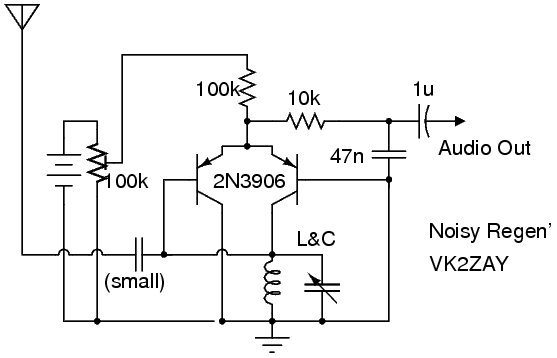
Description: The following circuit shows about Noisy Regen Receiver Circuit Diagram. Features: Noisy Regenerative Receiver Circuit, making it easier to integrate with common-grounded test equipment, used PNP transistors (2N3906). Component: Inductor, Transistor, Battery, Capacitor, Antenna, Resistor.
0 comments
 
Support : Creating Website | Johny Template | Mas Template
Copyright © 2011. The Circuit - All Rights Reserved
Template Created by Creating Website Published by Mas Template
Proudly powered by Blogger