Featured Post Today
print this page
Latest Post
Showing posts with label Automotive. Show all posts

Fog Lamp Switch Circuit

Description 
In most countries it is now mandatory or at least recommended to have a rear fog light on a trailer with the additional requirement that, when the trailer is coupled to the car, the rear fog light of the towing car has to be off. The circuit shown here is eminently suitable for this application. The circuit is placed near the rear fog light of the car. The 12-V connection to the lamp has to be interrupted and is instead connected to relay contacts 30 and 87A (K1, K3). When the rear fog light is turned on it will continue to operate normally.
Circuit Diagram:
 If a trailer with fog light is now connected to the trailer connector (7- or 13-way, K2), a current will flow through L1. L1 is a coil with about 8 turns, wound around reed contact S1. S1 will close because of the current through L1, which in turn energizes relay Re1 and the rear fog light of the car is switched off. The fog light of the trailer is on, obviously. The size of L1 depends on reed contact S1. The fog lamp is 21 W, so at 12 V there is a current of 1.75 A. L1 is sized for a current between 1.0 and 1.5 A, so that it is certain that the contact closes. The wire size has to be about 0.8 mm. The relay Re1 is an automotive relay that is capable of switching the lamp current. The voltage drop across L1 is negligible.
Source http://www.extremecircuits.net/2010/05/fog-lamp-switch-circuit.html
1 comments

Car-Bulb Flasher Circuit

Description 
This astonishingly simple circuit allows one or two powerful 12V 21W car bulbs to be driven in flashing mode by means of a power MosFet. Devices of this kind are particularly suited for road, traffic and yard alerts and in all cases where mains supply are not available but a powerful flashing light are yet necessary.
Circuit Diagram:


Parts:
  • R1 = 6.8K
  • R2 = 220K
  • R3 = 22K
  • C1 = 100uF-25V
  • C2 = 10u-25V
  • D1 = 1N4002
  • Q1 = BC557
  • Q2 = IRF530
  • LP1 = 12V-21W Car Filament Bulb (See Notes)
  • SW1 = SPST Switch (3 Amp minimum) 
Notes:
  • Flashing frequency can be varied within a limited range by changing C1 value.
  • As high dc currents are involved, please use suitably sized cables for battery and bulb(s) connections. 
Source http://www.extremecircuits.net/2009/07/car-bulb-flasher.html
3 comments

Automobile Interior Lights Fader Circuit

Circuit diagram 
Description
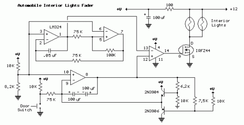
This circuit is similar to the fading eyes circuit above and is used to slowly brighten and fade interior lights of older cars.
The circuit is based around the LM324 low power opamp which draws around 3mA of current, so it won't bother the battery if left connected for extended periods.
The top two opamps (pins 1,2,3 and 5,6,7) form a triangle wave oscillator running at about 700Hz while the lower opamp (pins 8,9,10) produces a linear, 5 second ramp, that moves up or down depending on the position of the door switch. The two transistors and associated resistors serve to limit the ramp voltage to slightly more and less than the upper and lower limits of the triangle waveform. These two signals (700 hZ. triangle wave and 5 second ramp) are applied to the inputs of the 4th opamp (pins 12,13,14) that serves as a voltage comparator and generates a varying duty cycle square wave that controls the IRFZ44 MOSFET and lamp brightness. The 5 second fade time can be adjusted with the 75K resistor connected to the door switch. A larger value will increase the time and a smaller value will speed it up.
When the door switch is closed (car door open) the voltage on pin 8 slowly rises above the negative peaks of the triangle wave producing a short duty cycle output and a dim light. As the ramp moves farther positive, a greater percentage of the triangle wave will be lower than the ramp voltage producing a wider pulse and brighter light. This process continues until the ramp is 100% above the positive peaks of the triangle wave and the output is maximum. When the door switch is open, the reverse action takes place and the lamps slowly fade out.
The IRFZ44 shouldn't require a heat sink if the total load is 50 watts or less but the temperature of the MOSFET should be monitored to insure it doesn't overheat. The on-state resistance is only 0.028 ohms so that 4 amps of current (48 watts) is only around 100mW. For larger loads, a small heat sink can be added to keep the MOSFET cool.

0 comments

LED Bike Light Circuit Project Diagram

Description 
 On my mountain bike I always used to have one of those well-known flashing LED lights from the high street shop. These often gave me trouble with flat batteries and lights that fell off. As an electronics student I thought: “this can be done better”. First I bought another front wheel, one which has a dynamo already built in the hub. This supplied a nice sine wave of 30 Vpp (at no load). With this knowledge I designed a simple power supply. The transistors that are used are type BD911.
These are a bit of an over-kill, but there were plenty of these at my school, so that is why I used them. Something a little smaller will also work. The power supply is connected to an astable multi-vibrator. This alternately drives the front light and the rear light. The frequency is determined by the RC time-constant of R3 and C3, and R2 and C4. This time can be calculated with the formula: t = R3×C3 = 20×103×10×10-6 = 0.2 s You can use a 22k (common value) for R2 and R3, that doesn’t make much difference. On a small piece of prototyping board are six LEDs with a voltage dropping resistor in series with each pair of LEDs.
Circuit Diagram: 
 Such a PCB is used for both the front and the rear of the bike. Of course, you use white LEDs for the front and red ones for the rear. The PCB with the main circuit is mounted under the seat, where it is safe and has been working for more than a year now. There are a few things I would change for the next revision. An on/off switch would be nice. And if the whole circuit was built with SMD parts it could be mounted near the front light. This would also be more convenient when routing the wiring. Now the cable from the dynamo goes all the way to the seat and from there to the front and rear lights.

0 comments

Speed-limit Alert Circuit

Wireless portable unit
Adaptable with most internal combustion engine vehicles
Circuit Diagram
Parts:
  • R1,R2,R19 1K 1/4W Resistors
  • R3-R6,R13,R17 100K 1/4W Resistors
  • R7,R15 1M 1/4W Resistors
  • R8 50K 1/2W Trimmer Cermet
  • R9 470R 1/4W Resistor
  • R10 470K 1/4W Resistor
  • R11 100K 1/2W Trimmer Cermet (see notes)
  • R12 220K 1/4W Resistor (see notes)
  • R14,R16 68K 1/4W Resistors
  • R18 22K 1/4W Resistor
  • R20 150R 1/4W Resistor (see notes)
  • C1,C7 100µF 25V Electrolytic Capacitors
  • C2,C3 330nF 63V Polyester Capacitors
  • C4-C6 4µ7 25V Electrolytic Capacitors
  • D1,D5 Red LEDs 3 or 5mm.
  • D2,D3 1N4148 75V 150mA Diodes
  • D4 BZX79C7V5 7.5V 500mW Zener Diode
  • IC1 CA3140 or TL061 Op-amp IC
  • IC2 4069 Hex Inverter IC
  • IC3 4098 or 4528 Dual Monostable Multivibrator IC
  • Q1,Q2 BC238 25V 100mA NPN Transistors
  • L1 10mH miniature Inductor (see notes)
  • BZ1 Piezo sounder (incorporating 3KHz oscillator)
  • SW1 SPST Slider Switch
  • B1 9V PP3 Battery (see notes)
  • Clip for PP3 Battery 
 Device Purpose:
 This circuit has been designed to alert the vehicle driver that he has reached the maximum fixed speed limit (i.e. in a motorway). It eliminates the necessity of looking at the tachometer and to be distracted from driving. There is a strict relation between engine's RPM and vehicle speed, so this device controls RPM, starting to beep and flashing a LED once per second, when maximum fixed speed is reached. Its outstanding feature lies in the fact that no connection is required from circuit to engine.
Circuit operation:
 IC1 forms a differential amplifier for the electromagnetic pulses generated by the engine sparking-plugs, picked-up by sensor coil L1. IC2A further amplifies the pulses and IC2B to IC2F inverters provide clean pulse squaring. The monostable multivibrator IC3A is used as a frequency discriminator, its pin 6 going firmly high when speed limit (settled by R11) is reached. IC3B, the transistors and associate components provide timings for the signaling part, formed by LED D5 and piezo sounder BZ1. D3 introduces a small amount of hysteresis.
Notes:
  • D1 is necessary at set-up to monitor the sparking-plugs emission, thus permitting to find easily the best placement for the device on the dashboard or close to it. After the setting is done, D1 & R9 can be omitted or switched-off, with battery saving.
  • During the preceding operation R8 must be adjusted for better results. The best setting of this trimmer is usually obtained when its value lies between 10 and 20K.
  • You must do this first setting when the engine is on but the vehicle is stationary.
  • The final simplest setting can be made with the help of a second person. Drive the vehicle and reach the speed needed. The helper must adjust the trimmer R11 until the device operates the beeper and D5. Reducing car's speed the beep must stop.
  • L1 can be a 10mH small inductor usually sold in the form of a tiny rectangular plastic box. If you need an higher sensitivity you can build a special coil, winding 130 to 150 turns of 0.2 mm. enameled wire on a 5 cm. diameter former (e.g. a can). Extract the coil from the former and tape it with insulating tape making thus a stand-alone coil.
  • Circuit's current drawing is approx. 10mA. If you intend to use the car's 12V battery, you can connect the device to the lighter socket. In this case R20 must be 330R.
  • Depending on the engine's cylinders number, R11 can be unable to set the device properly. In some cases you must use R11=200K and R12=100K or less.
  • If you need to set-up the device on the bench, a sine or square wave variable generator is required.
  • To calculate the frequency relation to RPM in a four strokes engine you can use the following formula:
  • Hz= (Number of cylinders * RPM) / 120.
  • For a two strokes engine the formula is: Hz= (Number of cylinders * RPM) / 60.
  • Thus, for a car with a four strokes engine and four cylinders the resulting frequency @ 3000 RPM is 100Hz.
  • Temporarily disconnect C2 from IC1's pin 6. Connect the generator's output to C2 and Ground. Set the generator's frequency to i.e. 100Hz and regulate R11 until you hear the beeps and LED D5 flashes. Reducing the frequency to 99 or 98 Hz, beeping and flashing must stop.
  • This circuit is not suited to Diesel engines. 


Author: RED Free Circuit Designs
Source http://www.redcircuits.com/
0 comments
 
Support : Creating Website | Johny Template | Mas Template
Copyright © 2011. The Circuit - All Rights Reserved
Template Created by Creating Website Published by Mas Template
Proudly powered by Blogger