Featured Post Today
print this page
Latest Post
Showing posts with label Digital. Show all posts

Monostable Flip Flop Circuit

Description 
The monostable flip flop, sometimes called a 'one shot' is used to produce a single pulse each time it is triggered. It can be used to debounce a mechanical switch so that only one rising and one falling edge occurs for each switch closure, or to produce a delay for timing applications. In the discrete circuit, the left transistor normally conducts while the right side is turned off. Pressing the switch grounds the base of the conducting transistor causing it to turn off which causes the collector voltage to rise. As the collector voltage rises, the capacitor begins to charge through the base of the opposite transistor, causing it to switch on and produce a low state at the output. The low output state holds the left transistor off until the capacitor current falls below what is needed to keep the output stage saturated. When the output side begins to turn off, the rising voltage causes the left transistor to return to it's conducting state which lowers the voltage at it's collector and causes the capacitor to discharge through the 10K resistor (emitter to base). The circuit then remains in a stable state until the next input. The one shot circuit on the right employs two logic inverters which are connected by the timing capacitor. When the switch is closed or the input goes negative, the capacitor will charge through the resistor generating an initial high level at the input to the second inverter which produces a low output state. The low output state is connected back to the input through a diode which maintains a low input after the switch has opened until the voltage falls below 1/2 Vcc at pin 3 at which time the output and input return to a high state. The capacitor then discharges through the resistor (R) and the circuit remains in a stable state until the next input arrives. The 10K resistor in series with the inverter input (pin 3) reduces the discharge current through the input protection diodes. This resistor may not be needed with smaller capacitor values.
Circuit Diagram


Note:
These circuits are not re-triggerable and the output duration will be shorter than normal if the circuit is triggered before the timing capacitors have discharged which requires about the same amount of time as the output. For re-triggerable circuits, the 555 timer, or the 74123 (TTL), or the 74HC123 (CMOS) circuits can be used.

 Source http://www.bowdenshobbycircuits.info/page9.htm#mono.gif
1 comments

Digital Radar Speedometer Circuit

Circuit Diagram
Description
This circuit is a Digital Radar Speedometer. It allows us to evaluate the speed of any object moving, especially cars and other vehicles. The speed is calculated in kilometers per hour (KPH). Its display has three digits. This radar works with the laser reflexion. It sends laser radiation to the object and this object reflects the laser radiation to the radar. To evaluate the speed of a vehicle, we must be in front of it. In other words, the vehicle must come in our direction. The front of the radar must point the front of the vehicle. The radar has the shape of a pistol. In this radar, it has a laser LED and a laser diode. Both have a lens.
The laser LED can send a spot of light to a distance of 90 m (295 ft). It's very important that the distance range of the laser LED is 90 m, if not, the speed will not be calculated properly. The laser diode, which receives the light signal by the laser LED, must be able to detect the light which is same color as that emitted by the laser LED. The laser diode and the laser LED must be placed one beside the other. They are protected by a tinted pane. They must be placed at the front of the radar and point the outside. The radar is powered by a 9V battery and it has a SPST switch to control its power state.
The display, or the speed indicator, is placed at the rear of the radar, just on the right of the overload LED indicator. All the logic components of the circuit must be of the 74AS series and TTL type. Because they have short time of response (less than 1.7 ns) and have high frequency supports (more than 200 MHz). The radar can evaluate the speed of an object moving between 0 to 999 km/h. After this speed, the overload LED indicator will turn on and the "999" will still displayed. The radar displays the speed during 3 seconds, after this time, it displays "zero" (0).
Author: Serge Saati
E-mail: serge_saati@hotmail.com
Source: http://www.electronics-lab.com
0 comments

Digital AC/DC Voltage Tester Circuit Diagram

Description
It is always necessary for engineers and technicians to test AC/DC mains voltages and continuity for any given circuit during breakdowns, the above mentioned circuit can be used as and sought of tester and can also check the continuity for you. all one has to do is that to touch the two probes at the required terminal of either live or an dead circuit
The unique design of the tester allows the circuit to work in both AC and DC without any mode selector switch.
When the probes A and B are short circuited voltage pin 1 goes a little below the threshold of the Schmitt trigger due to the voltage divider action of the resistor R1, R2 and VR1 This disables the gate of pin1 and due to this the transistor T2 goes into saturation while the transistor T1 is cut off therefore the green LED glows while the red segment goes off and the display will now glow as “C” 
 Circuit Diagram

VR1 is a miniature preset which is to be calibrated before use its calibrations are fairy simple, keep both the probes A and B short circuited and the preset VR1 at its minimum value and slowly increase the resistance value of the VR1 till the red LED glows OFF and only green LED glows

Source http://www.electronguide.com/circuits_pages/Digital_AC-DC_Voltage.html
0 comments

USB Printer Share Switch Circuit Diagram Project

Description 
This simple device allows two computers to share a single USB printer or some other USB device, such as an external flash drive, memory card reader or scanner. A rotary switch selects the PC that you wish to use with the USB device, while two LEDs indicate the selected PC.
The most common way to share a USB printer between two PCs is to use one machine as a print server. However, that’s not always convenient because it means that the server PC must always be on if you want to print something. 
Real Circuit Image
That can be a real nuisance if you just want to quickly fire up the other machine and print something out. It also means that the two PCs must be networked together, either via a hub/router or directly via an ethernet crossover cable.
Another way is to use a dedicated USB print server. However, as before, this must be connected to an ethernet network, along with the PCs. Such devices also need their own power supply, generally cost well over $100 and are overkill if you just want to share a single USB printer between two computers for occasional printing in a home set-up. 
Circuit Layout: 

That’s where this simple device comes in. It’s basically a 2-way switch box that lets you manually switch your USB printer from one PC to the other, as required. The switching is performed using a rotary switch, while two LEDs on the front panel indicate which PC has been connected to the printer.
This method has several advantages. First, you don’t need to network your two computers. Second, you can print from either machine with the other turned off. And third, the device doesn’t need a power supply.
Circuit diagram:
 The circuit uses switch poles S1a-S1c to select either USB socket CON1 or CON2 and connect its pins through to CON3. The fourth pole (S1d) selects either LED1 or LED2, to indicate which PC has been selected.
0 comments

Digital Volt and Ampere Meter Circuit Diagram

Circuit Diagram 1
Circuit Diagram 2
 Circuit Diagram 3
Description
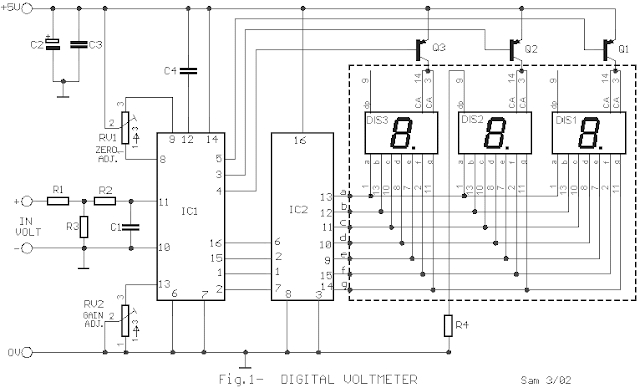
Even if the digital multimeters have dominated in a lot of applications, in the measurement, exist the need for existence of instruments of clue in various appliances, voltage and current, as in power supply or elsewhere. The circuits that give make this precisely the work, measure the voltage in terminal a circuit and the current that passes in his. The circuit does not present particular difficulties for somebody that has a small experience. The two circuits are the himself, with a small difference only in their input, when they have they measure voltage or current and in connection that concern decimal point [ dp ]. In the department of input IC1 and IC3, exist the CA3161E, that is a A/D Converter for 3-Digit Display. In the drive of Display IC2 and IC4, exist CA3161E, that is a BCD the Seven Segment Decoder/ Driver. As it appear in Fig.1, that concern the voltmeter in input [ + IN ], exist in series a what resistor R1 in combination with the R3 create a voltage divider. On the contrary in the Fig.2 that it concern the ampere meter, this resistor does not exist, because the circuit is connected differently, thus the current pass through the R5, creating a fall of voltage, in her terminal, proportional current that it pass from this.
Adjustments

Voltmeter: Short circuit in the input, pins 10 and 11 [IC1] and we regulate the RV1, until we take clue in the Display, zero in all the digits. We rectify and connect in the input a external voltage roughly 900mV. With the RV2, we regulate so that we take the clue 900mV in the Display. At the same time, we check this voltage with a external multimeter, of good quality and precision.

Amperemeter: Short circuit in the input, pins 10 and 11 [IC3] and we regulate the RV4, until we take clue in the Display, zero in all the digits. We rectify and we connect in + IN point, provided that we place in series with the positive pole, of battery, a resistor 10R/10W and in the –IN, a new battery 9V. We regulate the RV3 so that we take clue in the Display 0.90A. We check simultaneously the correctness of measurement with a external digital ambermeter.  A point that it should we are careful, the capacitors C4 and C9, it should they are very good quality. Also the various in the placement of resistors R4 and R7. of connection two circuits, for measurement voltage and current, appear in the Fig.3. The power supply that is public for two circuits appears in the Fig.4. If exist suitable constant supply in the appliance in which will be placed permanently the circuits, then can remove the T1 and bridge GR1 and is connected this voltage, in point A. The IC5 good is placed in heatsink.

Feature
V in maximum: 100V [99.9V]

A in maximum: 10A [9.99A]

Max. measurement Voltage Error: 100mV
Max. measurement Ampere Error: 100mA
Part List
R1=680Kohms C1-5=10nF IC2-4=CA3161E  Intersil-Harris
R2-6=1Mohms C2-6=47uF 16V IC5=7805
R3=6.8Kohms C3-7-10-11=100nF GR1=4X 1N4001
R4-7=270 ohms C4-8=220nF 1% Q1......6=BC557
R5=0.1 ohms 5W C9=2200uF 25V DS1......6= 7Segment Display common anode
RV1-4=50Kohms  trimmer 10 turns C12=10uF 16V T1=230VAC/6VAC 1A
RV2-3=5Kohms trimmer 10 turns IC1-3=CA3162E  Intersil-Harris
Source - http://users.otenet.gr/~%20athsam/digital_volt_and_ambere_meter_eng.htm
2 comments
 
Support : Creating Website | Johny Template | Mas Template
Copyright © 2011. The Circuit - All Rights Reserved
Template Created by Creating Website Published by Mas Template
Proudly powered by Blogger