Featured Post Today
print this page
Latest Post

Simple Logic Probe Circuit

Description 
This simple logic probe has both LEDs on with no signal at the input but due to the nor gates connected to the probe, indicates correctly when a high or low signal is present. It also works correctly for pulse trains. Normally both LEDs are forward biased and therefore on, powered by the 12V supply. When a logic "high" is present at the probe, IC1a's output goes low sending IC1b's output high. This turns off LED1 but forward-biases (and turns on) LED2. Conversely, a logic "low" at the probe will send IC1b low, turning LED1 on and LED2 off. 
Circuit Diagram:
Source http://www.extremecircuits.net/2010/05/simple-logic-probe.html
0 comments

Video Isolator Circuit Diagram

Description 
 These days many more audio-visual devices in the home are connected together. This is especially the case with the TV, which may be connected to a DVD player, a hard disk recorder, a surround-sound receiver and often a PC as well. This often creates a problem when earth loops are created in the shielding of the video cables, which may cause hum and other interference. The surround-sound receiver contains a tuner that takes its signal from a central aerial distribution system.
The TV is also connected to this and it’s highly likely that the PC has a TV-card, which again is connected to the same system. On top of this, there are many analogue connections between these devices, such as audio cables. The usual result of this is that there will be a hum in the audio installation, but in some cases you may also see interference on the TV screen.
The ground loop problem can be overcome by galvanically isolating the video connections, for example at the aerial inputs of the surround-sound receiver and the TV.
Special adaptors or filters are sold for this purpose, known as video ground loop isolators. Good news: such a filter can also be easily made at home by yourself. There are two ways in which you can create galvanic isolation in a TV cable. The first is to use an isolating transformer with two separate windings. The other is to use two coupling capacitors in series with the cable. The latter method is easily the simplest to implement and generally works well enough in practice. The simplest way to produce such a ‘filter’ is as an in-line adapter, so you can just plug it onto either end of a TV aerial cable.
Diagram and snapshoot:

The only requirements are a male and female coax plug and two capacitors. The latter have to be suitable for high-frequency applications, such as ceramic or MKT types. It is furthermore advisable to choose types rated for high voltages (400 V), since the voltages across these capacitors can be higher than you might expect (A PC that isn’t connected to the mains Earth can have a voltage as high as 115 V (but at a very low, safe current), caused by the filter capacitors in its power supply.
These capacitors don’t need to be high value ones, since they only have to pass through frequencies above about 50 MHz. Values of 1 nF or 2.2 nF are therefore sufficient. To make the isolator you should connect one capacitor between the two earth connections of the coax plugs and the other between the two signal connections. The mechanical construction has to be sturdy enough such that the connections to the capacitors won’t break whenever the inline adapter is removed forcibly.
A good way to do this is to make a cover from a piece of PVC piping for the central part. Wrap aluminium foil round the outside and connect it to one of the plugs, so that the internal parts are properly shielded from external interference. Make sure that the aluminium foil doesn’t make contact with the other plug, otherwise you lose the isolation. The majority of earth loops will disappear when you connect these filters to all used outputs of the central aerial distribution system where the signal enters the house.
 Author: Harry Baggen, Elektor Electronics 2008
Source http://www.extremecircuits.net/2010/05/video-isolator-circuit-diagram.html
0 comments

Dark Activated Terrace Lamp Circuit

Description
This device allows one or more lamps to illuminate at sunset and turn off at dawn.Q1 and Q2 form a trigger device for the SCR, providing short pulses at 100Hz frequency. Pulse duration is set by R2 and C1.When the light hits R1, the photo resistor assumes a very low resistance value, almost shorting C1 and preventing circuit operation. When R1 is in the dark, its resistance value becomes very high thus enabling circuit operation. 
Circuit Diagram:

Parts
  • R1 = LDR
  • R2 = 100K
  • R3 = 200K
  • R4 = 470R
  • R5 = 12K
  • R6 = 1K
  • R7 = 470R
  • C1 = 10nF-63V
  • D1 = TIC106D
  • D2 = 1N4007
  • D3 = 1N4007
  • D4 = 1N4007
  • D5 = 1N4007
  • Q1 = BD327
  • Q2 = BD337
  • SK1 = Female Mains Socket 
 Notes:
  • R3 allows fine setting of operating threshold and R2 value can be raised to 150K maximum.
  • Several lamps wired in parallel can be connected to the circuit, provided total power dissipation of the load does not exceed about 300 - 500W.
  • PL1 can be omitted and the input mains supply wires connected in parallel to any switch controlling lamps. In this case, if the switch is left open, the circuit will be able to drive the lamps; if the switch is closed, the lamps will illuminate and the circuit will be by-passed.
  • Warning! The circuit is connected to 230Vac mains, and then some parts in the circuit board are subjected to lethal potential! Avoid touching the circuit when plugged and enclose it in a plastic box. 
Source http://www.extremecircuits.net/2009/06/dark-activated-terrace-lamp_19.html
0 comments

16 Stage Bi-Directional LED Sequencer Circuit

Description 
The bi-directional sequencer uses a 4 bit binary up/down counter (CD4516) and two "1 of 8 line decoders" (74HC138 or 74HCT138) to generate the popular "Night Rider" display. A Schmitt Trigger oscillator provides the clock signal for the counter and the rate can be adjusted with the 500K pot. Two additional Schmitt Trigger inverters are used as a SET/RESET latch to control the counting direction (up or down). Be sure to use the 74HC14 and not the 74HCT14, the 74HCT14 may not work due to the low TTL input trigger level. When the highest count is reached (1111) the low output at pin 7 sets the latch so that the UP/DOWN input to the counter goes low and causes the counter to begin decrementing. When the lowest count is reached (0000) the latch is reset (high) so that the counter will begin incrementing on the next rising clock edge. The three lowest counter bits (Q0, Q1, Q2) are connected to both decoders in parallel and the highest bit Q3 is used to select the appropriate decoder. The circuit can be used to drive 12 volt/25 watt lamps with the addition of two transistors per lamp as shown below in the section below titled "Interfacing 5 volt CMOS to 12 volt loads" 
Circuit Diagram
 Source -http://www.bowdenshobbycircuits.info/
0 comments

2 Transistor FM Voice Transmitter

Warning: Take care with transmitter circuits. It is illegal in most countries to operate radio transmitters without a license. Although only low power this circuit may be tuned to operate over the range 87-108MHz with a range of 20 or 30 metres.
Circuit Diagram 
Notes
  • I have used a pair of BC548 transistors in this circuit. Although not strictly RF transistors, they still give good results. I have used an ECM Mic insert from Maplin Electronics, order code FS43W. It is a two terminal ECM, but ordinary dynamic mic inserts can also be used, simply omit the front 10k resistor. The coil L1 was again from Maplin, part no. UF68Y and consists of 7 turns on a quarter inch plastic former with a tuning slug. The tuning slug is adjusted to tune the transmitter. Actual range on my prototype tuned from 70MHz to around 120MHz. The aerial is a few inches of wire. Lengths of wire greater than 2 feet may damp oscillations and not allow the circuit to work. Although RF circuits are best constructed on a PCB, you can get away with veroboard, keep all leads short, and break tracks at appropriate points.
  • One final point, don't hold the circuit in your hand and try to speak. Body capacitance is equivalent to a 200pF capacitor shunted to earth, damping all oscillations. I have had some first hand experience of this problem.
.
Author: Andy Collinson, anc@mitedu.freeserve.co.uk
Source http://www.zen22142.zen.co.uk/
0 comments

Automobile Interior Lights Fader Circuit

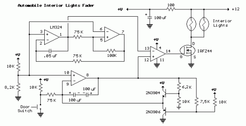
Circuit diagram 
Description
This circuit is similar to the fading eyes circuit above and is used to slowly brighten and fade interior lights of older cars.
The circuit is based around the LM324 low power opamp which draws around 3mA of current, so it won't bother the battery if left connected for extended periods.
The top two opamps (pins 1,2,3 and 5,6,7) form a triangle wave oscillator running at about 700Hz while the lower opamp (pins 8,9,10) produces a linear, 5 second ramp, that moves up or down depending on the position of the door switch. The two transistors and associated resistors serve to limit the ramp voltage to slightly more and less than the upper and lower limits of the triangle waveform. These two signals (700 hZ. triangle wave and 5 second ramp) are applied to the inputs of the 4th opamp (pins 12,13,14) that serves as a voltage comparator and generates a varying duty cycle square wave that controls the IRFZ44 MOSFET and lamp brightness. The 5 second fade time can be adjusted with the 75K resistor connected to the door switch. A larger value will increase the time and a smaller value will speed it up.
When the door switch is closed (car door open) the voltage on pin 8 slowly rises above the negative peaks of the triangle wave producing a short duty cycle output and a dim light. As the ramp moves farther positive, a greater percentage of the triangle wave will be lower than the ramp voltage producing a wider pulse and brighter light. This process continues until the ramp is 100% above the positive peaks of the triangle wave and the output is maximum. When the door switch is open, the reverse action takes place and the lamps slowly fade out.
The IRFZ44 shouldn't require a heat sink if the total load is 50 watts or less but the temperature of the MOSFET should be monitored to insure it doesn't overheat. The on-state resistance is only 0.028 ohms so that 4 amps of current (48 watts) is only around 100mW. For larger loads, a small heat sink can be added to keep the MOSFET cool.

0 comments

Wireless On-Off Switch Circuit

Descriptio 
Normally home appliances are controlled by means of switches, sensors, etc. However, physical contact with switches may be dangerous if there is any shorting. The circuit described here requires no physical contact for operating the appliance. You just need to move your hand between the infrared LED (D2) and the phototransistor (Q1). The infrared rays transmitted by D2 is detected by the phototransistor to activate the hidden lock, flush system, hand dryer or else. This circuit is very stable and sensitive compared to other AC appliance control circuits. It is simple, compact and cheap. Current consumption is low in milliamperes. The circuit is built around an IC CA3140, D2, phototransistor and other discrete components.  
Circuit Diagram:

Parts:
  • R1 = 470R
  • R2 = 100K
  • R3 = 3.3K
  • R4 = 10K
  • D1 = 1N4007
  • D2 = IR LED
  • Q1 = L14F1
  • RL = 5Vdc Relay
  • IC = CA3140
  • Q2 = BC548 
Circuit Operation:
When regulated 5V is connected to the circuit, D2 emits infrared rays, which are received by phototransistor Q1 if it is properly aligned. The collector of Q1 is connected to non-inverting pin 3 of IC1. Inverting pin 2 of IC1 is connected to voltage-divider preset R4. Using preset R4 you can vary the reference voltage at pin 2, which also affects sensitivity of the phototransistor. Op-amp IC1 amplifies the signal received from the phototransistor. Resistor R3 controls the base current of transistor BC548 (Q2). The high output of IC1 at pin 6 drives transistor Q2 to energies relay RL1 and switch on the appliance, say, hand dryer, through the relay contacts. The working of the circuit is simple. In order to switch on the appliance, you simply interrupt the infrared rays falling on the phototransistor through your hand. During the interruption, the appliance remains on through the relay. When you remove your hand from the infrared beam, the appliance turns off through the relay. Assemble the circuit on any general-purpose PCB. Identify the resistors through colour coding or using the multimeter. Check the polarity and pin configuration of the IC and mount it using base. After soldering the circuit, connect +5V supply to the circuit.
0 comments

Telephone Line Monitor Circuit

Circuit Diagram 

Description
 If you feel that somebody is tampering with your telephone line you might find this little circuit useful. It detects if there is another telephone connected to the line, if there is a short or an open line. Sound and a flashing light will tell you which is the current situation. The speaker is practically cut out during a normal conversation thus preserving privacy, only the LED will flash occasionally. The circuit does not require any battery and takes the supply from the telephone line itself. The transistors used are wired in a reversed biased fashion thus behaving as oscillators. You might try the 2N2222A as an alternative (not tested). This monitor is, of course, suitable only for analogue lines. Watch the polarity of the input line: the circuit will not be damaged by a polarity reversal but it will not operate correctly. 

Author: smartkit
Source http://www.electronics-lab.com/
0 comments

Powerful Security Siren Circuit

Description
This circuit was requested by several correspondents. Its purpose was to obtain more power than the siren circuit already available on this website (One-IC two-tones Siren) and to avoid the use of ICs. A complementary transistor pair (Q2 & Q3) is wired as a high efficiency oscillator, directly driving the loudspeaker. Q1 ensures a full charge of C2 when power is applied to the circuit. Pressing on P1, C2 gradually discharges through R8: the circuit starts oscillating at a low frequency that increases slowly until a high steady tone is reached and kept indefinitely. When P1 is released, the output tone frequency decreases slowly as C2 is charged to the battery positive voltage through R6 and the Base-Emitter junction of Q2. When C2 is fully charged the circuit stops oscillating, reaching a stand-by status.
Circuit Diagram:
 Parts:
  • P1 = SPST Pushbutton Operating Switch
  • R1 = 1K
  • R2 = 10K
  • R3 = 1K
  • R4 = 220R
  • R5 = 10K
  • R6 = 220K
  • R7 = 22K
  • R8 = 100K
  • C1 = 22uF-25V
  • C2 = 22uF-25V
  • C3 = 10nF-63V
  • C4 = 47uF-25V
  • Q1 = BC557
  • Q2 = BC557
  • Q3 = BC337
  • B1 = 12V Battery
  • SW1 = SPST Toggle or Slide Main Switch
  • SPKR = 8 Ohms Loudspeaker
Notes:
  • A good sized loudspeaker will ensure a better and powerful output tone.
  • As stand-by current drawing is zero, SW1 can be omitted and B1 wired directly to the circuit.
  • Maximum current drawing at full output is about 200mA.
Source http://www.eeweb.com/blog/extreme_circuits/powerful-security-siren
0 comments

A Hiqh Quality Headphone Amplifier Circuit

Description
Some lovers of High Fidelity headphone listening prefer the use of battery powered headphone amplifiers, not only for portable units but also for home “table” applications. This design is intended to fulfill their needs. An improved output driving capability is gained by making this a push-pull Class-B arrangement. Output power can reach 100mW RMS into a 16 Ohm load at 6V supply with low standing and mean current consumption, allowing long battery duration.
Circuit Diagram
Parts
  • P1 = 22K Potentiometer
  • R1 = 15K Resistor
  • R2 = 100K Resistor
  • R3 = 100K Resistor
  • R4 = 47K Resistor
  • R5 = 470R Resistor
  • R6 = 500R Resistor
  • R7 = 1K Resistor
  • R8 = 18K Resistor
  • R9 = 18K Resistor
  • R10 = 2.2R Resistor
  • R11 = 2.2R Resistor
  • R12 = 33R Resistor
  • R13 = 4.7K Resistor
  • C1 = 10uF-25V Capacitors
  • C2 = 10uF-25V Capacitors
  • C3 = 100nF-63V (PF)
  • C4 = 220uF-25V Capacitors
  • C5 = 100nF-63V (PF)
  • C6 = 220uF-25V Capacitors
  • Q1 = BC560C PNP Transistor
  • Q2 = BC560C PNP Transistor
  • Q3 = BC550C NPN Transistor
  • Q4 = BC550C NPN Transistor
  • Q5 = BC560C PNP Transistor
  • Q6 = BC327 PNP Transistor
  • Q7 = BC337 NPN Transistor
  • J1 = RCA Audio Input Socket
  • J2 = 3mm Stereo Jack Socket
  • B1 = 6V Battery Rechargeable
  • SW1=SPST Slide or Toggle Switch

Notes:
  • For a Stereo version of this circuit, all parts must be doubled except P1, SW1, J2 and B1.
  • Before setting quiescent current rotate the volume control P1 to the minimum, Trimmer R6 to maximum resistance and Trimmer R3 to about the middle of its travel.
  • Connect a suitable headphone set or, better, a 33 Ohm 1/2W resistor to the amplifier output.
  • Switch on the supply and measure the battery voltage with a Multimeter set to about 10Vdc fsd.
  • Connect the Multimeter across the positive end of C4 and the negative ground.
  • Rotate R3 in order to read on the Multimeter display exactly half of the battery voltage previously measured.
  • Switch off the supply, disconnect the Multimeter and reconnect it, set to measure about 10mA fsd, in series to the positive supply of the amplifier.
  • Switch on the supply and rotate R6 slowly until a reading of about 3mA is displayed.
  • Check again the voltage at the positive end of C4 and readjust R3 if necessary.
  • Wait about 15 minutes, watch if the current is varying and readjust if necessary.
  • Those lucky enough to reach an oscilloscope and a 1 KHz sine wave generator can drive the amplifier to the maximum output power and adjust R3 in order to obtain a symmetrical clipping of the sine wave displayed.
Technical data:
Output power (1 KHz sine wave):
  • 16 Ohm: 100mW RMS
  • 32 Ohm: 60mW RMS
  • 64 Ohm: 35mW RMS
  • 100 Ohm: 22.5mW RMS
  • 300 Ohm: 8.5mW RMS
Sensitivity:
  • 160mV input for 1V RMS output into 32 Ohm load (31mW)
  • 200mV input for 1.27V RMS output into 32 Ohm load (50mW)
Frequency response at 1V RMS:
  • Flat from 45Hz to 20 KHz, -1dB at 35Hz, -2dB at 24Hz
Total harmonic distortion into 16 Ohm load at 1 KHz:
  • 1V RMS (62mW) 0.015% 1.27V RMS (onset of clipping, 100mW) 0.04%
Total harmonic distortion into 16 Ohm load at 10 KHz:
  • 1V RMS (62mW) 0.05% 1.27V RMS (onset of clipping, 100mW) 0.1%
  • Unconditionally stable on capacitive load
 Source: http://www.redcircuits.com
0 comments
 
Support : Creating Website | Johny Template | Mas Template
Copyright © 2011. The Circuit - All Rights Reserved
Template Created by Creating Website Published by Mas Template
Proudly powered by Blogger