Description

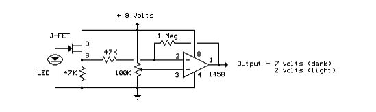
Here's a circuit that takes advantage of the photo-voltaic voltage of an
ordinary LED. The LED voltage is buffered by a junction FET transistor
and then applied to the inverting input of an op-amp with a gain of
about 20. This produces a change of about 5 volts at the output from
darkness to bright light. The 100K potentiometer can be set so that the
output is around 7 volts in darkness and falls to about 2 volts in
bright light.
Circuit Diagram


Post a Comment