Description
Circuit Diagram

Parts


Source -http://www.elektroda.pl/
This circuit enables you to test quartz resonators at the range values
from 32kHz to 24MHz. Confirmation of good state of quartz resonator is
done by diode signalling LED and acoustic signal. Switch S2 enables
change of range .
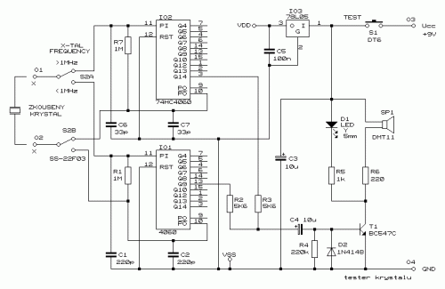
Parts
- R1,R7 1 M
- R2,R3 5,6 k
- R4 220 K
- R5 1 k
- R6 220
- C1,C2 220 pF
- C3,C4 10 F/25V RSM
- C5 100 nF
- C6,C7 33 pF
- D1 LED 5 mm, yellow
- D2 1N4148
- T1 BC547C
- IO1 4060
- IO2 74HC4060
- IO3 78L05
- S1 push button (normally open)
- S2 Two-positional switch
Source -http://www.elektroda.pl/


Post a Comment