Featured Post Today
print this page
Latest Post
Showing posts with label Audio. Show all posts

Hearing Aid Circuit

Description 
Commercially available hearing aids are quite costly. Here is an inexpensive hearing aid circuit that uses just four transistors and a few passive components. 
Circuit Diagram

Parts:
  • R1 = 2.2K
  • R2 = 680K
  • R3 = 3.3k
  • R4 = 220K
  • R5 = 1.5K
  • R6 = 220R
  • R7 = 100K
  • R8 = 680K
  • C1 = 104pF
  • C2 = 104pF
  • C3 = 1uF/10V
  • C4 = 100uF/10V
  • C5 = 100uF/10V
  • Q1 = BC549
  • Q2 = BC548
  • Q3 = BC548
  • Q4 = BC558
  • J1 = Headphone jack
  • B1 = 2x1.5V Cells
  • SW1 = On/Off-Switch
Circuit Operation:
On moving power switch SW1 to ‘on’ position, the condenser microphone detects the sound signal, which is amplified by Q1 and Q2. Now the amplified signal passes through coupling capacitor C3 to the base of Q3.
The signal is further amplified by Q4 to drive a low impedance earphone. Capacitors C4 and C5 are the power supply decoupling capacitors. The circuit can be easily assembled on a small, general-purpose PCB or a Vero board.
It operates off a 3V DC supply. For this, you may use two small 1.5V cells. Keep switch S to ‘off’ state when the circuit is not in use. To increase the sensitivity of the condenser microphone, house it inside a small tube.
 Author: www.electronicsforu.com
  Source http://www.extremecircuits.net/2009/07/hearing-aid.html
0 comments

Three Channel Audio Splitter Circuit

Description 
This circuit is suitable to amplify and distribute the audio signals. The input audio signal is applied to the J1 and after passing through the P1, It is buffered and amplified by the IC1 prepared to redistribute. It has 3 outputs to drive 3 audio lines with 300 ohms impedance.
Circuit Diagram:
Parts:
  • J1 = RCA Socket (See Notes)
  • P1 = 100K-Potentiometre
  • R* = 10K-100K
  • R1 = 560K
  • R2 = 1K
  • R3 = 2.2K
  • R4 = 2.7K
  • R5 = 2.7K
  • R6 = 330R
  • R7 = 330R
  • R8 = 330R
  • C1 = 100uF-25V
  • C2 = 100uF-25V
  • C3 = 100uF-25V
  • D1 = BZX79C18
  • D2 = BZX79C18
  • Q1 = BC337
  • Q2 = BC327
  • IC1 = NE5532-34 
Notes:
  • J1 will be RCA Audio input female socket.
  • R* is on your choice it can be choose between 10K to 100K resistor.
  • Output capacitor’s value is between 100uf to 470uf and power handling is 25V to 50V.
  • You can power up this circuit via +12V/-12V regulated supply but you have to remove following parts Q1-Q2-C2-C3-D1-D2.
  • Maximum power ratings +35V/-35V
Source  http://www.extremecircuits.net/2009/07/3-channel-audio-splitter.html
0 comments

Multitone Siren Circuit

Description 
This multi-tone siren is useful for burglar alarms, reverse horns, etc. It produces five different audio tones and is much more ear-catching than a single-tone siren. The circuit is built around popular CMOS oscillator-cum-divider IC 4060 and small audio amplifier LM386. IC 4060 is used as the mult-itone generator. A 100µH inductor is used at the input of IC 4060. So it oscillates within the range of about 5MHz RF. IC 4060 itself divides RF signals into AF and ultrasonic ranges. Audio signals of different frequencies are available at pins 1, 2, 3, 13 and 15 of IC 4060 (IC1).
Circuit Diagram:
These multi-frequency signals are mixed and fed to the audio amplifier built around IC LM386. The output of IC2 is fed to the speaker through capacitor C9. If you want louder sound, use power amplifier TBA810 or TDA1010. Only five outputs of IC1 are used here as the other five outputs (pins 4 through 7 and 14) produce ultrasonic signals, which are not audible. Assemble the circuit on a general-purpose PCB and enclose in a suitable cabinet. Regulated 6V-12V (or a battery) can be used to power the circuit.

 Author: PradeeP G., Elektor Electronics Magazine
Source http://www.extremecircuits.net/2010/05/multitone-siren.html
0 comments

Sound Effects Generator Circuit

Description: 
 This circuit uses a UM3561 IC to produce four different sound effects.
Circuit Diagram
Notes:
 Nothing too complicated here. The IC produces all the sound effects, the output at Pin 3 being amplified by the transistor. A 64 ohm loudspeaker can be substituted in place of the 56 ohm resistor and 8 ohm loudspeaker. The 2 pole 4 way switch controls the sound effects. Position 1 (as drawn) being a Police siren, position 2 is a fire engine sound, 3 is an ambulance and position 4 is a machine gun effect. The IC is manufactured by UMC and was available from Maplin electronics code UJ45Y. At the time of writing this has now been discontinued, but they have have limited stocks available.

Author: Andy Collinson, anc@mitedu.freeserve.co.uk
Source http://www.zen22142.zen.co.uk/
0 comments

Loudspeaker Protection 2 for P.A output

Description 
The circuit protection output of power amplifiers and loudspeakers, dispose certain interesting elements, as the isolation of loudspeakers from the exit of amplifier, when is presented continuous voltage in his exit or when the temperature of heatsink, goes up excessively, providing simultaneously and time delay in the connection loudspeakers in the amplifier, so that we avoid pass in them, the known annoying noises from the charge - discharge of capacitors of supply. It’s constituted by a binary comparator [ IC1 ], the transistors Q1-2 and indicative LED D5-6. The supply of circuit can become from positive voltage [ Point A ] of mainly power supply, which is stabilised by the D3 and the R17, in + 15V. Point B is connected in one of the secondary AC coil of main transformer. If close the main switch of main line AC, then a AC voltage (in secondary coil of transformer), is presented in the point B, it’s rectified from the D2 and it supply with negative voltage, via the R9, the Q3, this cut off and it begin charge the C4 via the R10-11. As long as time therefore last the charge of capacitor, the input [+] of comparator IC2B is found in low level concerning input [-]. The exit of IC2B, has low level, therefore the Q4 remain in cutt off and the RL1 remain deactivate, the D6 he is ON. Just the C4 charged, change the situation of IC1B, is activated the RL1, the loudspeaker are connected in the amplifier output, the D6 it OFF. When it’s interrupted the supply, all the process is inverted, and the loudspeaker disconnect, without pass annoying noises. If as long as it work the circuit, is presented problem of continuous voltages in the exit of amplifier then turn off of RL1 and protected the loudspeakers. This become with help the Q1-2. The acoustic signal from the exit of power amplifier, is led to point D, the alternate voltages is led to the ground via the C1-2, that create a not polar capacitor. Continuous voltages, bigger than + 1.7V or smaller than –4.8V, activate immediately the Q1 or the Q2, respectively. With the activation of transistors goes down the level of input [+] of IC1B, so that turn off and the RL1. A other section of protection that for us provide the circuit is the thermic protection. This become with the help of sensor temperature the RTH, which is a resistor of type PTC (positive factor of temperature), and is found placed above in heatsink, where are found also the power transistors. Her price increase, with the increase of temperature, until the potential in input [-] of IC1A, goes up above from the level of input [+], which is determined with the voltage divider R2-3. As soon as the level in input [-] exceed the level of input [+], the exit of IC1A, it return in low level, compelling and the IC2B to change situation, turn off the RL1 and to turn on the D5, that show the thermic protection. In the circuit the limit above which it exist clue of thermic protection they are 70?C. If it’s presented instability, in this stage, in operation of RL1, should be changed the R4, with other of smaller price. The circuit was published in magazine “Elektor” 12/95. 
Circuit Diagram
Part List
  • R1-2=27 Kohms
  • R3=1.4 Kohms
  • R4=1 Mohms
  • R5-14-17=3.3 Kohms
  • R6-7=100 Kohms
  • R8=47 Kohms
  • R9-11=120 Kohms
  • R10=470 Kohms
  • R12=15 Kohms
  • R13=1.5 Kohms
  • R15=4.7 Kohms
  • R16=33 Kohms
  • R18=1.5 Kohms 5W
  • RTH=KTY81-122
  • C1-2=100uF 63V
  • C3=470nF 100V MKT
  • C4-5=47uF 25V
  • IC1=LM393
  • Q1-2-3=BC337
  • Q4=BC639
  • D1=1N4148
  • D2=1N4004
  • D3=15V 1.5W Zener
  • D4=1N4002
  • D5-6=LED
  • RL1=24V Relay 
Source -http://users.otenet.gr/~athsam/protection_2_EN.htm
0 comments

Audio Tone Control Circuit

Description
The LM1036 is a DC controlled tone (bass/treble), volume and balance circuit for stereo applications in car radio, TV and audio systems. An additional control input allows loudness compensation to be simply effected. Four control inputs provide control of the bass, treble, balance and volume functions through application of DC voltages from a remote control system or, alternatively, from four potentiometers which may be biased from a zener regulated supply provided on the circuit. Each tone response is defined by a single capacitor chosen to give the desired characteristic.
Circuit Diagram

Features
Wide supply voltage range, 9V to 16V
Large volume control range, 75 dB typical
Tone control, ±15 dB typical
Channel separation, 75 dB typical
Low distortion, 0.06% typical for an input level of 0.3 Vrms
High signal to noise, 80 dB typical for an input level of 0.3 Vrms
Few external components required .
Note: Vcc can be anything between 9V to 16V and the output capacitors are 10uF/25V electrolytic.
0 comments

Simple White Noise Generator Circuit

Description 
This two-transistor white noise generator has a surprising feature – about 30dB more noise than the more traditional designs. Q1 and Q2 can be any small-signal transistors with a beta of up to 400. The reverse-biased emitter-base junction of Q1 provides the noise source, which is fed into the base of Q2. Q2 forms a simple amplifier with a gain of 45dB. The improved output level is due mainly to the inclusion of C1, which provides a low-impedance AC source to the noise source while not disturbing the DC bias of Q1. 
Circuit Diagram:
 The low amount of feedback also makes this circuit very resistant to oscillations and tolerant to circuit layout. Unfortunately, the truism of "no such thing as free lunch" also applies; C1 makes the circuit very sensitive to power supply ripple.
Source - http://www.extremecircuits.net/2010/04/simple-white-noise-generator.html
1 comments

SOUND ACTIVATED RELAY Circuit

Description
This Relay remains dormant until the op-amp activates upon sound via the electret-microphone.   I only tested the 2-wire type. The input stage is a regular off-the-shelf 741 operational amplifier and connected as a non-inverting follower audio amplifier.
Gain is approximately 100 which you can raise by increasing the value of R2.
The amplified signal is rectified and filtered via C3,D1/D2, and R3 to an acceptable DC level D1 and D2 can be any signal diode like 1N914, 1N4148 or the NTE519.
Cx can be anything with a value of 6.8 to 22µF. Adjust if necessary. Cbias is to DC-couple the mic to the input of the 741. 
Circuit Diagram
Q1, the 2N2222 or 2N3904 is a general purpose NPN transistor and is not critical. The NTE123A will work too.
Potentiometer R4 is used to set the audio level to a desired sensitivity value to activate the relay via transistor Q1. Diode D3 is mounted over the relay coil to absorb sparks when the relay opens.
Cathode goes to ‘+’.
The op-amp configuration in this particular drawing needs a dual voltage power-supply which can be made from two 9 volts alkaline batteries.
0 comments

Pure Class-A Headphone Amplifier Circuit Schematic

Description 
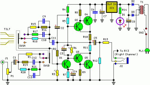
This design is derived from the Portable Headphone Amplifier featuring an NPN/PNP compound pair emitter follower output stage. An improved output driving capability is gained by making this a push-pull Class-A arrangement. Output power can reach 427mW RMS into a 32 Ohm load at a fixed standing current of 100mA. The single voltage gain stage allows the easy implementation of a shunt-feedback circuitry giving excellent frequency stability. 
Tilt control:
 The mentioned shunt-feedback configuration also allows the easy addition of frequency dependent networks in order to obtain an useful, unobtrusive, switchable Tilt control (optional). When SW1 is set in the first position a gentle, shelving bass lift and treble cut is obtained. The central position of SW1 allows a flat frequency response, whereas the third position of this switch enables a shelving treble lift and bass cut.
Circuit Diagram:
 Parts
  • P1 = 22K Dual gang Log Potentiometer (ready for Stereo)
  • R1 = 15K 1/4W Resistor
  • R2 = 220K 1/4W Resistor
  • R3 = 100K 1/2W Trimmer Cermet
  • R4 = 33K 1/4W Resistor
  • R5 = 68K 1/4W Resistor
  • R6 = 50K 1/2W Trimmer Cermet
  • R7 = 10K 1/4W Resistor
  • R8 = 47K 1/4W Resistors
  • R9 = 47K 1/4W Resistors
  • R10 = 2R2 1/4W Resistors
  • R11 = 2R2 1/4W Resistors
  • R12 = 4K7 1/4W Resistor
  • R13 = 4R7 1/2W Resistor
  • R14 = 1K2 1/4W Resistor
  • R15 = 330K 1/4W Resistors (Optional)
  • R16 = 680K 1/4W Resistor (Optional)
  • R17 = 220K 1/4W Resistors (Optional)
  • R18 = 330K 1/4W Resistors (Optional)
  • R19 = 220K 1/4W Resistors (Optional)
  • R20 = 22K 1/4W Resistors (Optional)
  • R21 = 22K 1/4W Resistors (Optional)
  • C1 = 10µF 25V Electrolytic Capacitors
  • C2 = 10µF 25V Electrolytic Capacitors
  • C3 = 10µF 25V Electrolytic Capacitors
  • C4 = 10µF 25V Electrolytic Capacitors
  • C5 = 220µF 25V Electrolytic Capacitors
  • C6 = 100nF 63V Polyester Capacitors
  • C7 = 220µF 25V Electrolytic Capacitors
  • C8 = 2200µF 25V Electrolytic Capacitor
  • C9 = 1nF 63V Polyester Capacitors (Optional)
  • C10 = 470pF 63V Polystyrene or Ceramic Capacitor (Optional)
  • C13 = 15nF 63V Polyester Capacitor (Optional)
  • C11 = 1nF 63V Polyester Capacitors (Optional)
  • C12 = 1nF 63V Polyester Capacitors (Optional)
  • D1 = 5mm. or 3mm. LED
  • D2 = 1N4002 100V 1A Diodes
  • D3 = 1N4002 100V 1A Diodes
  • Q1 = BC550C 45V 100mA Low noise High gain NPN Transistors
  • Q2 = BC550C 45V 100mA Low noise High gain NPN Transistors
  • Q3 = BC560C 45V 100mA Low noise High gain PNP Transistor
  • Q4 = BD136 45V 1.5A PNP Transistor
  • Q5 = BD135 45V 1.5A NPN Transistor
  • IC1 = 7815 15V 1A Positive voltage regulator IC
  • T1 = 220V Primary, 15+15V Secondary-5VA Mains transformer
  • SW1 = 4 poles 3 ways rotary Switch (ready for Stereo)
  • SW2 = SPST slide or toggle Switch
  • J1 = RCA audio input socket
  • J2 = 6mm. or 3mm. Stereo Jack socket
  • PL1 = Male Mains plug
Notes:
  1. Q4, Q5 and IC1 must be fitted with a small U-shaped heatsink.
  2. For a Stereo version of this circuit, all parts must be doubled except P1, IC1, R14, D1, D2, D3, C8, T1, SW1, SW2, J2 and PL1.
  3. If the Tilt Control is not needed, omit SW1, all resistors from R15 onwards and all capacitors from C9 onwards. Connect the rightmost terminal of R1 to the Base of Q1.
  4. Before setting quiescent current rotate the volume control P1 to the minimum, Trimmer R6 to zero resistance and Trimmer R3 to about the middle of its travel.
  5. Connect a suitable headphone set or, better, a 33 Ohm 1/2W resistor to the amplifier output.
  6. Connect a Multimeter, set to measure about 10Vdc fsd, across the positive end of C5 and the negative ground.
  7. Switch on the supply and rotate R3 in order to read about 7.7-7.8V on the Multimeter display.
  8. Switch off the supply, disconnect the Multimeter and reconnect it, set to measure at least 200mA fsd, in series to the positive supply of the amplifier.
  9. Switch on the supply and rotate R6 slowly until a reading of about 100mA is displayed.
  10. Check again the voltage at the positive end of C5 and readjust R3 if necessary.
  11. Wait about 15 minutes, watch if the current is varying and readjust if necessary.
  12. Those lucky enough to reach an oscilloscope and a 1KHz sine wave generator, can drive the amplifier to the maximum output power and adjust R3 in order to obtain a symmetrical clipping of the sine wave displayed.
Technical data:

Output power (1KHz sinewave):
  • 32 Ohm: 427mW RMS
  • 64 Ohm: 262mW RMS
  • 100 Ohm: 176mW RMS
  • 300 Ohm: 64mW RMS
  • 600 Ohm: 35mW RMS
  • 2000 Ohm: 10mW RMS
Sensitivity:
  1. 140mV input for 1V RMS output into 32 Ohm load (31mW)
  2. 500mV input for 3.5V RMS output into 32 Ohm load (380mW)
  3. Total harmonic distortion into 32 Ohm load @ 1KHz:
  4. 1V RMS 0.005% 3V RMS 0.015% 3.65V RMS (onset of clipping) 0.018%
  5. Total harmonic distortion into 32 Ohm load @ 10KHz:
  6. 1V RMS 0.02% 3V RMS 0.055% 3.65V RMS (onset of clipping) 0.1%
  7. Unconditionally stable on capacitive loads 
Souce  http://www.extremecircuits.net/2009/12/pure-class-headphone-amplifier.html
1 comments

Microphone Pre-amplifier Circuit Diagram Using LM348 IC

Circuit Diagram
Description
Here is the circuit diagram of three input microphone preamplifier. This is a mic mixer preamplifier centered on the high gain operational amplifier IC LM 348. This IC LM 348 is a quad operational amplifier IC that is it has four operational amplifiers embedded in this chip. This IC has also got some advanced features such as very high gain, class AB output stage and very low input supply current of 0.6 mA for each op-amp.
The 3 channels of mic input require three amplifiers. The three op-amps (IC1b, IC1c and IC1d) out of four in the IC LM 348 are used here as input amplifiers for the corresponding channels. This three input amplifiers are made in this circuit work as non-inverting amplifiers. The operational amplifier IC1a is the output amplifier in this circuit. IC1a is wired as inverting amplifier here. The output from each input amplifiers are given to the inverting terminal of output op-amp. IC1a mixes the signals from each channel and produces the required output.
Notes
  • Use a good quality PCB to assemble this circuit.
  • IC LM 348 operates from a dual power supply. A +12/-12V DC dual supply is used here for powering the circuit.
  • The gain of individual channels can be adjusted by using potentiometers R5, R6 and R7.

0 comments

Amplified Ear Circuit Diagram

Description 
 This circuit, connected to 32 Ohm impedance mini-earphones, can detect very remote sounds. Useful for theatre, cinema and lecture goers: every word will be clearly heard. You can also listen to your television set at a very low volume, avoiding to bother relatives and neighbors. Even if you have a faultless hearing, you may discover unexpected sounds using this device: a remote bird twittering will seem very close to you.
Circuit Diagram:
Parts:
  • P1 = 22K
  • R1 = 10K
  • R2 = 1M
  • R3 = 4K7
  • R4 = 100K
  • R5 = 3K9
  • R6 = 1K5
  • R7 = 100K
  • R8 = 100R
  • R9 = 10K
  • C1 = 100nF 63V
  • C2 = 100nF 63V
  • C3 = 1µF 63V
  • C4 = 10µF 25V
  • C5 = 470µF 25V
  • C6 = 1µF 63V
  • D1 = 1N4148
  • Q1 = BC547
  • Q2 = BC547
  • Q3 = BC547
  • Q4 = BC337
  • J1 = Stereo 3mm. Jack socket
  • B1 = 1.5V Battery (AA or AAA cell etc.)
  • SW1 = SPST Switch (Ganged with P1)
  • MIC1 = Miniature electret microphone 
 Circuit Operation :
 The heart of the circuit is a constant-volume control amplifier. All the signals picked-up by the microphone are amplified at a constant level of about 1 Volt peak to peak. In this manner very low amplitude audio signals are highly amplified and high amplitude ones are limited. This operation is accomplished by Q3, modifying the bias of Q1 (hence its AC gain) by means of R2. A noteworthy feature of this circuit is 1.5V battery operation. Typical current drawing: 7.5mA.

Notes:

  1. Due to the constant-volume control, some users may consider P1 volume control unnecessary. In most cases it can be omitted, connecting C6 to C3. In this case use a SPST slider or toggle switch as SW1.
  2. Please note the stereo output Jack socket (J1) connections: only the two inner connections are used, leaving open the external one. In this way the two earpieces are wired in series, allowing mono operation and optimum load impedance to Q4 (64 Ohm).
  3. Using suitable miniature components, this circuit can be enclosed in a very small box, provided by a clip and hanged on one's clothes or slipped into a pocket.
  4. Gary Pechon from Canada reported that the Amplified Ear is so sensitive that he can hear a whisper 7 meters across the room.
  5. He hooked a small relay coil to the input and was able to locate power lines in his wall. He was also able to hear the neighbor's stereo perfectly: he could pick up the signals sent to the speaker voice coil through a plaster wall.
  6. Gary suggests that this circuit could make also a good electronic stethoscope. 
Author: www.redcircuits.com
Source http://www.extremecircuits.net/2009/06/amplified-ear_28.html
0 comments

Door Phone Circuit Schematic Diagram

Circuit Schematic Diagram
Description
This circuit can be used in front doors for visitors to communicate or it can be wired up in the front gate for conversation, this circuit is fairly simple but its worth, it dose not use any sought of condenser mic for voice transmission if uses the speaker for both the transmission purpose and for the reception purpose, the heart of the circuit is the operational amplifier LM386 which is used to amplify the voice signal gain adjust is provided by the 5k preset and the pot resistor 10k is used as the volume control.

Source - http://www.electronguide.com/circuits_pages/Doorphonecircuit.html
0 comments

Condenser Mic Audio Amplifier Circuit Diagram

Description
The compact, low-cost condenser mic audio amplifier described here provides good-quality audio of 0.5 watts at 4.5 volts. It can be used as part of intercoms, walkie-talkies, low-power transmitters, and packet radio receivers. Transistors T1 and T2 form the mic preamplifier. Resistor R1 provides the necessary bias for the condenser mic while preset VR1 functions as gain control for varying its gain. In order to increase the audio power, the low-level audio output from the preamplifier stage is coupled via coupling capacitor C7 to the audio power amplifier built around BEL1895 IC.
Circuit Diagram
BEL1895 is a monolithic audio power amplifier IC designed specifically for sensitive AM radio applications that delivers 1 watt into 4 ohms at 6V power supply voltage. It exhibits low distortion and noise and operates over 3V-9V supply voltage, which makes it ideal for battery operation. A turn-on pop reduction circuit prevents thud when the power supply is switched on. Coupling capacitor C7 determines low-frequency response of the amplifier. Capacitor C9 acts as the ripple-rejection filter.

Capacitor C13 couples the output available at pin 1 to the loudspeaker. R15-C13 combination acts as the damping circuit for output oscillations. Capacitor C12 provides the boot strapping function. This circuit is suitable for low-power HAM radio transmitters to supply the necessary audio power for modulation. With simple modifications it can also be used in intercom circuits.
 Author: D. Prabakaran ,Electronics For You Mag
0 comments

Microphone Circuit Test Oscillator Diagram

Description
This unit would be mounted in a small plastic or preferably metal box, with a 9V battery, level control, a male XLR connector (same as on a mic) and a switch.  Current drain is low, since the circuit only uses one dual opamp.  There is no need for a high quality device, and a 1458 is all that is needed.
Circuit Diagram
The first stage is the oscillator itself.  This is a simple three stage phase shift oscillator - a circuit that is remarkably uncommon - which is to say I have never seen it used elsewhere.  I designed it for another project a few years ago, and I don't understand why it is not more common.
If you want to tune it, you can use a 50k pot instead of R1.  I suggest that if tuned, set it to A-440 Hz.  Frequency stability is not wonderful, and it changes by a few Hertz as the battery discharges, but this is unlikely to cause problems - it is a test oscillator, not a tuning standard.  As shown, frequency will be about 430Hz, depending on the accuracy of the capacitors.
The phase shift network (R1-C1, R2-C2 and R3-C3) serves two purposes.  First (and for an oscillator, most importantly), it shifts the phase of the output signal so the feedback is positive, causing oscillation.  Secondly, since it is a three stage filter, it attenuates the signal and filters the output square wave so the signal at pin 2 is a reasonable sine wave.  Distortion (if you really care) is about 3% or so - I didn't measure it this time, but I recall having done so before.
The second stage is the output buffer, and the signal is simply split to supply the two mic leads.  The metal case should be connected to pin 1 (earth) on the XLR connector.  The output level control must be a linear type, as the circuit loading will create a good approximation to a log pot.  Maximum output into a typical microphone input will be about 100mV (unloaded oscillator output on mine was 140mV).
Not much to it - the whole circuit can be built on a small piece of veroboard, and the battery, pot and XLR connector will take up far more room than the oscillator.  There is no LED indicator for power, as this would draw more current than the circuit.  To prevent accidentally turning it on, a slide switch is suggested.  They are a pig to mount compared to a toggle switch, but are much less easily bumped.  If you can get a pot with a switch, this would be even better, but these are now hard to get - especially as linear.
Rod Elliott (ESP)
0 comments

Song Number Display Circuit Diagram

Circuit Diagram

Description
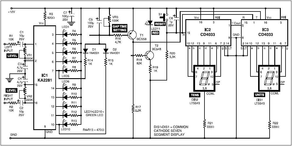
Here’s a circuit to display the song number in an audio system for quick reference to songs. It also serves the purpose of an extra visual indicator in modern audio systems.When the power is switched on, the power-on-reset circuit comprising 3.3k resistor R20 and 1µF, 25V capacitor C6 resets the counters, showing ‘00’ in the display. One can also reset the display to zero at any time by pressing reset switch S1.
When the first song starts playing, the output pins of IC1 (KA2281) go low and capacitor C5 starts charging. This forward biases transistor T1 and hence the input to IC3 at pin 1 goes to high state. As a result, the output of the counter goes to the next state, showing 01 on the display. The counter remains in this state until the song is completed.During the time gap before the next song starts playing, capacitor C5 discharges. After discharging of capacitor C5, the input to IC3 becomes low again. When the song starts, the process described above is repeated and the display shows 02. You can adjust VR3 to change the time gap setting. This must be set such that the circuit doesn’t respond to short gaps, if any, within a song and responds only to long gaps between different songs.Transistor T2 helps in gap-delay adjustment.
The intensity of LED11 diminishes when a song is completed and the counter is ready to accept the next pulse.Connect the input to the preamp output or equaliser output of the audio system. Adjust VR1 and VR2 to get the correct audio-level indication. If you are already using KA2281 for audio-level indication, just connect diodes D1 and D2 as shown in this circuit.Note that the counter counts the songs by detecting the gaps. Therefore any long gap within a song may cause false triggering and the display will also be incremented. However, as this is very unlikely to happen, the circuit shows the correct song number almost all the time.
0 comments

LM386 Audio Amp IC Internal Circuit Diagram

LM386 had been used for long time as an audio amplifier IC for low power applications. The schematic herein shows the LM386 internal circuit schematic.

 LM386 can be seen in three flavors, there are LM386-1, LM386-2 and LM386-3. Each of device provides 0.3W, 0.5W and 0.7W respectively.

0 comments

Sound Controlled Filp Flop Circuit Diagram

Description
Described here is a very inexpensive solution to many phono-controlled applications like remote switching on, for instance, or activating a camera, tape recorder, burglar alarms, toys, etc. The circuit given here employs a condenser microphone as the pick-up. A two-stage amplifier built around a quad op-amp IC LM324 offers a good gain to enable sound pick-up upto four metres. The third op-amp is configured as a level detector whose non-inverting terminal is fed with the amplified and filtered signal available at the output of the second op-amp. The inverting input of the third op-amp is given a reference voltage from a potential divider consisting of a 10k resistor and a 4.7k preset. The 100-ohm resistance in series with the potential divider ensures against the mis-triggering of the circuit by noise. Thus by adjusting the preset one can control the sensitivity (threshold) of the circuit. The sensitivity control thus helps in rejecting any external unwanted sounds which may be picked up by the amplifier. The output of the level detector are square pulses which are used to trigger a flip-flop. The 100mF capacitor connected across the supply also helps in bypassing noise.
Circut Diagram
A well regulated supply is recommended for proper functioning of the circuit because an unregulated supply can cause noise pulses to appear in the supply rails when the circuit changes-over state (especially when a load is connected to the circuit). These pulses can be picked up by the sensitive amplifier which will cause the circuit to again switch-over states, resulting into motor-boating noise. Since the circuit operates at 4.5V, it can be easily incorporated in digital circuits. Fig. (b) shows how the circuit can be employed to control the direction of a DC motor. The circuit employs four npn transistors. Transistors T1 and T4 have their bases tied together and they switch-on simultaneously when Q output is logic 1. Similarly T2 and T3 conduct when Q output is logic 1. Thus current through the motor changes direction when the flip-flop toggles. Filters connected in the circuit and tuned to different bands of audio frequencies will enable the same circuit to control more than one device. For instance, a high frequency sound (such as whistle) can switch on device 1 and a low frequency sound (such as clapping) can control device 2.
Source -http://www.electronic-circuits-diagrams.com/audioimages/audiockt9.shtml
0 comments

Cuckoo Sound Generator Circuit Diagram

Description 
This circuit generates a two-tone effect very much alike the cuckoo song. It can be used for door-bells or other purposes thanks to a built-in audio amplifier and loudspeaker. Used as a sound effect generator it can be connected to external amplifiers, tape recorders etc. In this case, the built-in audio amplifier and loudspeaker may be omitted and the output taken across C8 and ground. There are two options: free running, when SW1 is left open, and one-shot, when SW1 is closed. In this case a two-tone cuckoo song will be generated at each P1 pressing.
Circuit diagram:
Parts:

  • R1,R5___________1K 1/4W Resistors
  • R2_____________50K 1/2W Trimmer Cermet
  • R3______________8K2 1/4W Resistor
  • R4_____________82K 1/4W Resistor
  • R6______________1M 1/4W Resistor
  • R7,R17,R20,R21_22K 1/4W Resistors
  • R8,R10,R11,R19_10K 1/4W Resistors
  • R9____________150K 1/4W Resistor
  • R12_____________4K7 1/4W Resistor
  • R13___________100K 1/4W Resistor
  • R14___________220R 1/4W Resistor
  • R15,R22________20K 1/2W Trimmers Cermet
  • R16____________10R 1/4W Resistor
  • R18___________200K 1/2W Trimmer Cermet
  • C1,C11_________47nF 63V Polyester or Ceramic Capacitors
  • C2,C10,C12____220µF 25V Electrolytic Capacitors
  • C3____________220nF 63V Polyester or Ceramic Capacitor
  • C4_____________22nF 63V Polyester or Ceramic Capacitor
  • C5,C6,C8,C9___100nF 63V Polyester or Ceramic Capacitors
  • C7,C13,C14_____10µF 63V Electrolytic Capacitors
  • D1,D2,D3,D6__1N4148 75V 150mA Diodes
  • D4,D5_________BAT46 100V 150mA Schottky-barrier Diodes
  • Q1,Q2_________BC547 45V 100mA NPN Transistors
  • IC1____________7555 or TS555CN CMos Timer IC
  • IC2____________4093 Quad 2 input Schmitt NAND Gate IC
  • IC3____________4017 Decade counter with 10 decoded outputs IC
  • IC4___________LM386 Audio power amplifier IC
  • P1_____________SPST Pushbutton
  • SW1____________SPST Switch
  • SPKR___________8 Ohm Loudspeaker 

Circuit operation:

IC1 is wired as a square wave generator and produces both tones of the cuckoo song. The frequency of the higher one (667Hz) is set by means of Trimmer R2. When IC2D output goes low, a further Trimmer (R22) is added to IC1 timing components via D6, and the lower tone (545Hz) is generated. To imitate closely the cuckoo song, the square wave output of IC1 is converted to a quasi-sinusoidal wave form by R3, R4, C3 and C4, then mixed with the white noise generated by Q1, R6.
Q2 has two purposes: it mixes the two incoming signals and gates the resulting tone, shaping its attack and decay behavior by means of the parts wired around its Emitter. IC4 is the audio power amplifier driving the speaker and R15 is the volume control. The various sound and pause timings for the circuit are provided by the clock generator IC2A driving the decade counter IC3. Some output pins of this IC are gated by IC2C, IC2D and related components to drive appropriately the sound generator and the sound gate.
When SW1 is left open the circuit operates in the free-running mode and the cuckoo song is generated continuously. When SW1 is closed, the circuit generates two tones then stops, because a high state appears at the last output pin (#11) of the decade counter IC: therefore the count is inhibited by means of D1 feeding pin #13. The circuit is reset by a positive pulse at pin #15 of IC3 when P1 is pressed. 
Setup: 
Best results will be obtained if the two tones frequencies are set precisely, i.e. 667Hz for the first tone and 545Hz for the second: in musical terms this interval is called a Minor Third. Obviously a digital frequency counter, if available, would be the best tool to setup R2 and R22, but you can use a musical instrument, e.g. a piano or guitar, tuning-up the notes accurately by ear.
  • Disconnect temporarily R22 from D6 anode.
  • Connect the digital frequency counter to pin 3 of IC1.
  • Adjust R2 in order to read 667Hz on the display.
  • Connect R22 to negative ground and adjust it to read 545Hz on the display.
  • Restore R22 - D6 connection. 
Tuning by ear:

  • Disconnect temporarily R22 from D6 anode.
  • Disconnect C8 from Q2 Collector and connect it to R4, C4 and C5 junction.
  • Adjust R2 in order that the tone generated by the loudspeaker is at the same pitch of the reference note generated by your musical instrument. This reference note will be the E written on the stave in the fourth space when using the treble clef.
  • Connect R22 to negative ground and adjust it in order that the tone generated by the loudspeaker is at the same pitch of the reference note generated by your musical instrument. This second reference note will be the C-sharp written on the stave in the third space when using the treble clef.
  • Restore R22 - D6 and C8 to Q2 Collector connections.
Notes:

  • The master clock can be adjusted by means of R18.
  • The percentage of hiss and sound in the mixing circuit, setting the tone character, can be varied changing R8 and R7 values respectively.
  • Any kind of dc voltage supply in the 12 - 15V range can be used, but please note that supply voltages below 12V will prevent operation of the white noise generator.
  • An amusing application of this circuit is to use a photo-resistor in place of P1, then placing the unit near the flashing lamps of your Christmas tree. A sweet cuckoo song will be heard each time the lamp chosen will illuminate. 
Source - http://www.extremecircuits.net/2010/01/cuckoo-sound-generator-circuit.html
0 comments

High Quality Intercom Circuit Diagram

Description:
A very high quality intercom, which may also be used for room monitoring.
Circuit diagram
Notes:
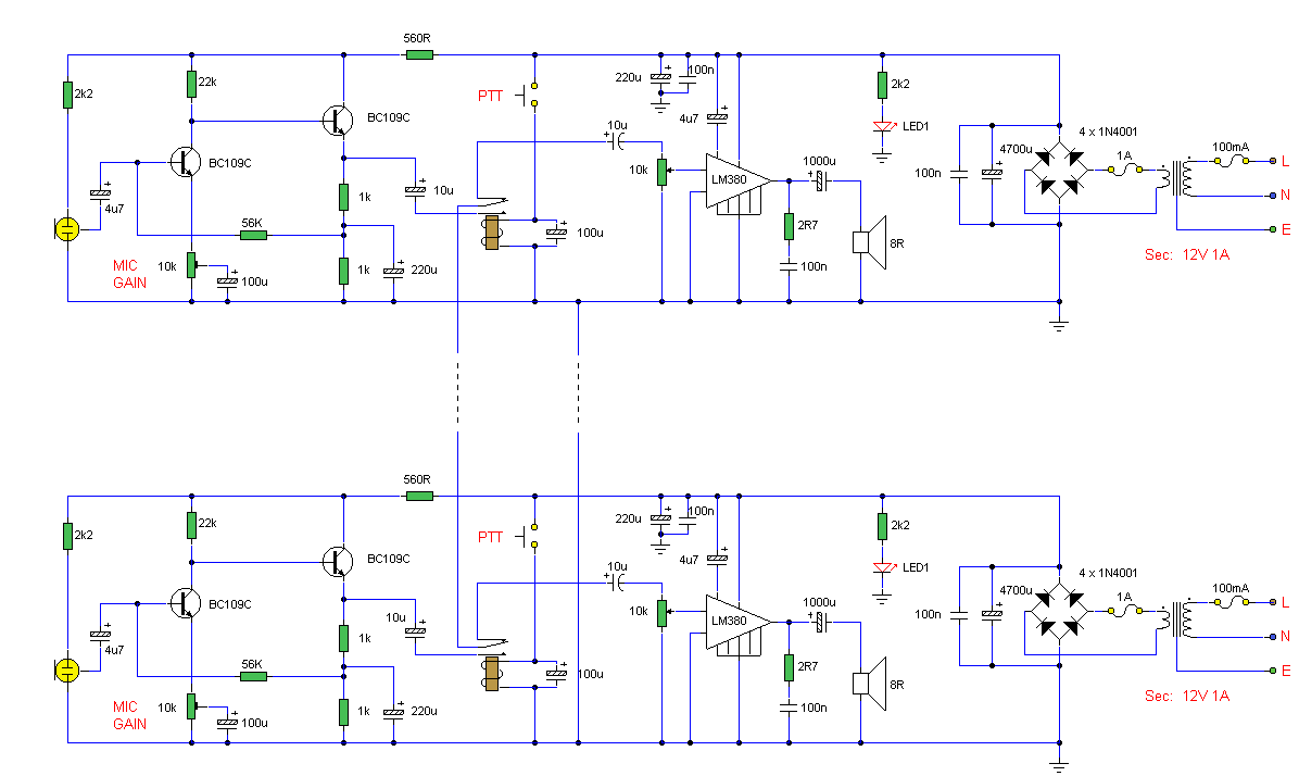
This circuit consists of two identical intercom units. Each unit contains a power supply, microphone preamplifier, audio amplifier and a Push To Talk (PTT) relay circuit. Only 2 wires are required to connect the units together. Due to the low output impedance of the mic preamp, screened cable is not necessary and ordinary 2 core speaker cable, or bell wire may be used.
The schematic can be broken into 34 parts, power supply, mic preamp, audio amplifierand PTT circuit. The power supply is designed to be left on all the time, which is why no on / off switch is provided. A standard 12 V RMS secondary transformer of 12VA will power the unit. Fuses are provided at the primary input and also secondary, before the rectifier. The 1 A fuse needs to be a slow blow type as it has to handle the peak rectifier current as the power supply electrolytics charge from zero volts.
The microphone amplifier is a 2 transistor direct coupled amplifier. BC108B transistors will work equally well in place of the BC109C transistors. The microphone used is a 3 terminal electret condenser microphone insert. These are popular and require a small current to operate. The preamp is shown in my audio circuit section as well, but has a very high gain and low distortion. The last transistor is biased to around half the supply voltage; this provides the maximum overload margin for loud signals or loud voices. The gain may be adjusted with the 10k preset. Sensitivity is very high, and a ticking clock can easily be heard from the distant loudspeaker.
The amplifier is based on the popular National Semiconductor LM380. A 50 mV input is all thats required to deliver 2W RMS into an 8 ohm loudspeaker. The choice of loudspeaker determines overall sound quality. A small loudspeaker may not produce a lot of bass, I used an old 8 inch radio loudspeaker. The 4.7u capacitor at pin 1 of the LM380 helps filter out any mains hum on the power supply. This can be increased to a 10u capacitor for better power supply rejection ratio.
The push to talk (PTT) circuit is very simple. A SPDT relay is used to switch between mic preamplifier output or loudspeaker input. The normally closed contact is set so that each intercom unit is "listening". The non latching push button switch must be held to talk. The 100u capacitor across the relay has two functions. It prevents the relays back emf from destroying the semiconductors, and also delays the release of the relay. This delay is deliberate, and prevents any last word from being "chopped" off.
Setting Up and Testing:
This circuit does not include a "call" button. This is simply because it is designed to be left on all the time, someone speaking from one unit will be heard in the other, and vice versa. Setup is simple, set to volume to a comfortable level, and adjust the mic preset while speaking with "normal volume" from one meter away. You do not need to be in close contact with the microphone, it will pick up a conversation from anywhere in a room. If the units are a long way away, there is a tendency for the cable to pick up hum, or radio interference. There are various defenses against this. One way is to use a twisted pair cable, each successive turn cancels the interference from the turn before. Another method is to use a small capacitor of say 100n between the common terminal of each relay and ground. This shunts high frequency signals to earth. Another method is to use a low value resistor of about 1k. This will shunt interference and hum, but will shunt the speech signal as well. However as the output impedance of each mic preamp is low, and the speech signals are also low, this will have little effect on speech but reduce interference to an acceptable level.
IC Pinout:
The LM380 pinout viewed from above is shown below on the left. In the schematic, the LM380 has been represented as a triangle, the pins are shown on the right hand diagram. Pins marked "NC" have no connection and are not used.
PCB Layout:
Corey Rametta has kindly drafted a PCB layout for this project. First an oversized version to show component placement. Note the tracks on the bottom side, components on the top side.
 Below is the actual size version shown track side.

Author: Andy Collinson
E-mail: anc@mitedu.freeserve.co.uk
Source: http://www.zen22142.zen.co.uk
0 comments

Automatic Loudness Control

Circuit diagram:

Parts
  • P1 10K Linear Potentiometer (Dual-gang for stereo)
  • R1,R6,R8 100K 1/4W Resistors
  • R2 27K 1/4W Resistor
  • R3,R5 1K 1/4W Resistors
  • R4 1M 1/4W Resistor
  • R7 20K 1/2W Trimmer Cermet
  • C1 100nF 63V Polyester Capacitor
  • C2 47nF 63V Polyester Capacitor
  • C3 470nF 63V Polyester Capacitor
  • C4 15nF 63V Polyester Capacitor
  • C5,C9 1µF 63V Electrolytic or Polyester Capacitors
  • C6,C8 47µF 63V Electrolytic Capacitors
  • C7 100pF 63V Ceramic Capacitor
  • IC1 TL072 Dual BIFET Op-Amp
  • SW1 DPDT Switch (four poles for stereo)
Comments:
 In order to obtain a good audio reproduction at different listening levels, a different tone-controls setting should be necessary to suit the well known behaviour of the human ear. In fact, the human ear sensitivity varies in a non-linear manner through the entire audible frequency band, as shown by Fletcher-Munson curves. A simple approach to this problem can be done inserting a circuit in the preamplifier stage, capable of varying automatically the frequency response of the entire audio chain in respect to the position of the control knob, in order to keep ideal listening conditions under different listening levels. Fortunately, the human ear is not too critical, so a rather simple circuit can provide a satisfactory performance through a 40dB range. The circuit is shown with SW1 in the "Control-flat" position, i.e. without the Automatic Loudness Control. In this position the circuit acts as a linear preamplifier stage, with the voltage gain set by means of Trimmer R7. Switching SW1 in the other position the circuit becomes an Automatic Loudness Control and its frequency response varies in respect to the position of the control knob by the amount shown in the table below. C1 boosts the low frequencies and C4 boosts the higher ones. Maximum boost at low frequencies is limited by R2; R5 do the same at high frequencies.
Technical data: 
 Frequency response referred to 1KHz and different control knob positions:
Total harmonic distortion at all frequencies and 1V RMS output: < 0.01%
Notes: 

  • SW1 is shown in "Control flat" position.
  • Schematic shows left channel only, therefore for stereo operation all parts must be doubled except IC1, C6 and C8.
  • Numbers in parentheses show IC1 right channel pin connections.
  • R7 should be set to obtain maximum undistorted output power from the amplifier with a standard music programme source and P1 rotated fully clockwise. 
 Author: RED Free Circuit Designs
Source http://www.redcircuits.com/
0 comments
 
Support : Creating Website | Johny Template | Mas Template
Copyright © 2011. The Circuit - All Rights Reserved
Template Created by Creating Website Published by Mas Template
Proudly powered by Blogger