Featured Post Today
print this page
Latest Post
Showing posts with label Automotive. Show all posts

Fog Lamp Switch Circuit

Description 
In most countries it is now mandatory or at least recommended to have a rear fog light on a trailer with the additional requirement that, when the trailer is coupled to the car, the rear fog light of the towing car has to be off. The circuit shown here is eminently suitable for this application. The circuit is placed near the rear fog light of the car. The 12-V connection to the lamp has to be interrupted and is instead connected to relay contacts 30 and 87A (K1, K3). When the rear fog light is turned on it will continue to operate normally.
Circuit Diagram:
 If a trailer with fog light is now connected to the trailer connector (7- or 13-way, K2), a current will flow through L1. L1 is a coil with about 8 turns, wound around reed contact S1. S1 will close because of the current through L1, which in turn energizes relay Re1 and the rear fog light of the car is switched off. The fog light of the trailer is on, obviously. The size of L1 depends on reed contact S1. The fog lamp is 21 W, so at 12 V there is a current of 1.75 A. L1 is sized for a current between 1.0 and 1.5 A, so that it is certain that the contact closes. The wire size has to be about 0.8 mm. The relay Re1 is an automotive relay that is capable of switching the lamp current. The voltage drop across L1 is negligible.
Source http://www.extremecircuits.net/2010/05/fog-lamp-switch-circuit.html
1 comments

Car-Bulb Flasher Circuit

Description 
This astonishingly simple circuit allows one or two powerful 12V 21W car bulbs to be driven in flashing mode by means of a power MosFet. Devices of this kind are particularly suited for road, traffic and yard alerts and in all cases where mains supply are not available but a powerful flashing light are yet necessary.
Circuit Diagram:


Parts:
  • R1 = 6.8K
  • R2 = 220K
  • R3 = 22K
  • C1 = 100uF-25V
  • C2 = 10u-25V
  • D1 = 1N4002
  • Q1 = BC557
  • Q2 = IRF530
  • LP1 = 12V-21W Car Filament Bulb (See Notes)
  • SW1 = SPST Switch (3 Amp minimum) 
Notes:
  • Flashing frequency can be varied within a limited range by changing C1 value.
  • As high dc currents are involved, please use suitably sized cables for battery and bulb(s) connections. 
Source http://www.extremecircuits.net/2009/07/car-bulb-flasher.html
3 comments

Automobile Interior Lights Fader Circuit

Circuit diagram 
Description
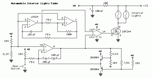
This circuit is similar to the fading eyes circuit above and is used to slowly brighten and fade interior lights of older cars.
The circuit is based around the LM324 low power opamp which draws around 3mA of current, so it won't bother the battery if left connected for extended periods.
The top two opamps (pins 1,2,3 and 5,6,7) form a triangle wave oscillator running at about 700Hz while the lower opamp (pins 8,9,10) produces a linear, 5 second ramp, that moves up or down depending on the position of the door switch. The two transistors and associated resistors serve to limit the ramp voltage to slightly more and less than the upper and lower limits of the triangle waveform. These two signals (700 hZ. triangle wave and 5 second ramp) are applied to the inputs of the 4th opamp (pins 12,13,14) that serves as a voltage comparator and generates a varying duty cycle square wave that controls the IRFZ44 MOSFET and lamp brightness. The 5 second fade time can be adjusted with the 75K resistor connected to the door switch. A larger value will increase the time and a smaller value will speed it up.
When the door switch is closed (car door open) the voltage on pin 8 slowly rises above the negative peaks of the triangle wave producing a short duty cycle output and a dim light. As the ramp moves farther positive, a greater percentage of the triangle wave will be lower than the ramp voltage producing a wider pulse and brighter light. This process continues until the ramp is 100% above the positive peaks of the triangle wave and the output is maximum. When the door switch is open, the reverse action takes place and the lamps slowly fade out.
The IRFZ44 shouldn't require a heat sink if the total load is 50 watts or less but the temperature of the MOSFET should be monitored to insure it doesn't overheat. The on-state resistance is only 0.028 ohms so that 4 amps of current (48 watts) is only around 100mW. For larger loads, a small heat sink can be added to keep the MOSFET cool.

0 comments

LED Bike Light Circuit Project Diagram

Description 
 On my mountain bike I always used to have one of those well-known flashing LED lights from the high street shop. These often gave me trouble with flat batteries and lights that fell off. As an electronics student I thought: “this can be done better”. First I bought another front wheel, one which has a dynamo already built in the hub. This supplied a nice sine wave of 30 Vpp (at no load). With this knowledge I designed a simple power supply. The transistors that are used are type BD911.
These are a bit of an over-kill, but there were plenty of these at my school, so that is why I used them. Something a little smaller will also work. The power supply is connected to an astable multi-vibrator. This alternately drives the front light and the rear light. The frequency is determined by the RC time-constant of R3 and C3, and R2 and C4. This time can be calculated with the formula: t = R3×C3 = 20×103×10×10-6 = 0.2 s You can use a 22k (common value) for R2 and R3, that doesn’t make much difference. On a small piece of prototyping board are six LEDs with a voltage dropping resistor in series with each pair of LEDs.
Circuit Diagram: 
 Such a PCB is used for both the front and the rear of the bike. Of course, you use white LEDs for the front and red ones for the rear. The PCB with the main circuit is mounted under the seat, where it is safe and has been working for more than a year now. There are a few things I would change for the next revision. An on/off switch would be nice. And if the whole circuit was built with SMD parts it could be mounted near the front light. This would also be more convenient when routing the wiring. Now the cable from the dynamo goes all the way to the seat and from there to the front and rear lights.

0 comments

Speed-limit Alert Circuit

Wireless portable unit
Adaptable with most internal combustion engine vehicles
Circuit Diagram
Parts:
  • R1,R2,R19 1K 1/4W Resistors
  • R3-R6,R13,R17 100K 1/4W Resistors
  • R7,R15 1M 1/4W Resistors
  • R8 50K 1/2W Trimmer Cermet
  • R9 470R 1/4W Resistor
  • R10 470K 1/4W Resistor
  • R11 100K 1/2W Trimmer Cermet (see notes)
  • R12 220K 1/4W Resistor (see notes)
  • R14,R16 68K 1/4W Resistors
  • R18 22K 1/4W Resistor
  • R20 150R 1/4W Resistor (see notes)
  • C1,C7 100µF 25V Electrolytic Capacitors
  • C2,C3 330nF 63V Polyester Capacitors
  • C4-C6 4µ7 25V Electrolytic Capacitors
  • D1,D5 Red LEDs 3 or 5mm.
  • D2,D3 1N4148 75V 150mA Diodes
  • D4 BZX79C7V5 7.5V 500mW Zener Diode
  • IC1 CA3140 or TL061 Op-amp IC
  • IC2 4069 Hex Inverter IC
  • IC3 4098 or 4528 Dual Monostable Multivibrator IC
  • Q1,Q2 BC238 25V 100mA NPN Transistors
  • L1 10mH miniature Inductor (see notes)
  • BZ1 Piezo sounder (incorporating 3KHz oscillator)
  • SW1 SPST Slider Switch
  • B1 9V PP3 Battery (see notes)
  • Clip for PP3 Battery 
 Device Purpose:
 This circuit has been designed to alert the vehicle driver that he has reached the maximum fixed speed limit (i.e. in a motorway). It eliminates the necessity of looking at the tachometer and to be distracted from driving. There is a strict relation between engine's RPM and vehicle speed, so this device controls RPM, starting to beep and flashing a LED once per second, when maximum fixed speed is reached. Its outstanding feature lies in the fact that no connection is required from circuit to engine.
Circuit operation:
 IC1 forms a differential amplifier for the electromagnetic pulses generated by the engine sparking-plugs, picked-up by sensor coil L1. IC2A further amplifies the pulses and IC2B to IC2F inverters provide clean pulse squaring. The monostable multivibrator IC3A is used as a frequency discriminator, its pin 6 going firmly high when speed limit (settled by R11) is reached. IC3B, the transistors and associate components provide timings for the signaling part, formed by LED D5 and piezo sounder BZ1. D3 introduces a small amount of hysteresis.
Notes:
  • D1 is necessary at set-up to monitor the sparking-plugs emission, thus permitting to find easily the best placement for the device on the dashboard or close to it. After the setting is done, D1 & R9 can be omitted or switched-off, with battery saving.
  • During the preceding operation R8 must be adjusted for better results. The best setting of this trimmer is usually obtained when its value lies between 10 and 20K.
  • You must do this first setting when the engine is on but the vehicle is stationary.
  • The final simplest setting can be made with the help of a second person. Drive the vehicle and reach the speed needed. The helper must adjust the trimmer R11 until the device operates the beeper and D5. Reducing car's speed the beep must stop.
  • L1 can be a 10mH small inductor usually sold in the form of a tiny rectangular plastic box. If you need an higher sensitivity you can build a special coil, winding 130 to 150 turns of 0.2 mm. enameled wire on a 5 cm. diameter former (e.g. a can). Extract the coil from the former and tape it with insulating tape making thus a stand-alone coil.
  • Circuit's current drawing is approx. 10mA. If you intend to use the car's 12V battery, you can connect the device to the lighter socket. In this case R20 must be 330R.
  • Depending on the engine's cylinders number, R11 can be unable to set the device properly. In some cases you must use R11=200K and R12=100K or less.
  • If you need to set-up the device on the bench, a sine or square wave variable generator is required.
  • To calculate the frequency relation to RPM in a four strokes engine you can use the following formula:
  • Hz= (Number of cylinders * RPM) / 120.
  • For a two strokes engine the formula is: Hz= (Number of cylinders * RPM) / 60.
  • Thus, for a car with a four strokes engine and four cylinders the resulting frequency @ 3000 RPM is 100Hz.
  • Temporarily disconnect C2 from IC1's pin 6. Connect the generator's output to C2 and Ground. Set the generator's frequency to i.e. 100Hz and regulate R11 until you hear the beeps and LED D5 flashes. Reducing the frequency to 99 or 98 Hz, beeping and flashing must stop.
  • This circuit is not suited to Diesel engines. 


Author: RED Free Circuit Designs
Source http://www.redcircuits.com/
0 comments

Automobile Indicator Circuit

Circuit Diagram
Description
The trafficating system in an automobile generally consists of two blinkers in the front and two blinkers at the rear, and their will be a small monitor lamp on the dash board for drivers indication. The blinker lamps are 12V, 18W rating and the monitor lamp is 12V 1W rating, a high power Alloy junction pnp transistor AD149 is used in this circuit. The blinking rate is 90 times per minute.
This circuit is suitable for installation in vehicles having 12v supply. The transistor Q1 and Q2 forms the basic multivibrator with a triggering frequency of about 90 pulses per minute; transistor Q3 performs the function of the switch. There are interstate coupling arrangements between the multivibrator, the switching stage and the monitor stage.
0 comments

LED 12 Volt Lead Acid Battery Meter Circuit

Description 
In the circuit below, a quad voltage comparator (LM339) is used as a simple bar graph meter to indicate the charge condition of a 12 volt, lead acid battery. A 5 volt reference voltage is connected to each of the (+) inputs of the four comparators and the (-) inputs are connected to successive points along a voltage divider. The LEDs will illuminate when the voltage at the negative (-) input exceeds the reference voltage. Calibration can be done by adjusting the 2K potentiometer so that all four LEDs illuminate when the battery voltage is 12.7 volts, indicating full charge with no load on the battery. At 11.7 volts, the LEDs should be off indicating a dead battery. Each LED represents an approximate 25% change in charge condition or 300 millivolts, so that 3 LEDs indicate 75%, 2 LEDs indicate 50%, etc. The actual voltages will depend on temperature conditions and battery type, wet cell, gel cell etc.
Circuit Diagram
 Source -http://www.bowdenshobbycircuits.info/
0 comments

Nite Rider Lights Circuit Schematic Diagram


Circuit Schematic Diagram

The circuit is drawn with PCB 123 which you can download for free from 
As a keen cyclist I am always looking for ways to be seen at night. I wanted something that was a novelty and would catch the motorists eye. So looking around at my fellow cyclists rear lights, I came up with the idea of 'NITE-RIDER'. NINE extra bright LED's running from left to right and right to left continuously. It could be constructed with red LEDs for use on the rear of the bike or white LED's for an extra eye catcher on the front of the bike.
All IC's are CMOS devices so that a 9V PP3 battery can be used, and the current drawn is very low so that it will last as long as possible.
Parts
1 555 timer IC4.
1 4027 flip flop IC1.
2 4017 Decade Counter IC2 and IC3.
3 4071 OR gate IC5, IC6 and IC7.
1 470 Ohm resistor 1/4 watt R3.
2 10K resistors 1/4 watt R1 and R2.
1 6.8UF Capasitor 16V C1.
9 Super brght LED's 1 to 9.
1 9V PP3 Battery.
1 single pole switch SW1.
1 Box.
How The Circuit Works.
IC4, C1, R1 and R2 are used for the clock pulse which is fed to both the counters IC2 and IC3 Pin 14.
IC1 is a Flip Flop and is used as a switch to enable ether IC2 or IC3 at pin 13.
IC7a detects when ether IC2 or IC3 has reached Q9 of the counter pin 11.
IC5, IC6 and IC7a protects the outputs of the counters IC2 and IC3 using OR gates which is then fed to the Anodes of the
LED's 1 to 9.

Author: Paul Hill
E-mail: hillpa@ntlworld.com
Source: http://www.electronics-lab.com
0 comments

Motorcycle Alarm Circuit Diagram and PCB for Prevent Steal.

Description
This project is prevented steal circuit which be kit to be easy the system is simple. but We thinks the project should be help to protect your motorcycle or accessories. This principle is simple be the system Close Wire Loop.
Circuit Diagram
The circuit is going to make a noise to warn that circuit turn , with the circuit used power electric energy while standby very low 0.5 uAmp. When relay working as a result use current about 70mAmp . The usability can use in an automobile,house door, leak round a house or the other. That time an electric line turn system , Relay command sent beep danger circuit work immediately.
0 comments

Automotive 12V to +-20V converter (for audio amplifier) Circuit Diagram

The limitation of car supply voltage (12V) forces to convert the voltages to higher in order to power audio amplifiers.

In fact the max audio power x speaker (with 4 ohm impedance) using 12V is (Vsupply+ - Vsupply-)^2/(8*impedance) 12^2/32 = 4.5Watts per channel, that is laughable...

For powering correctly an amplifier the best is to use a symmetric supply with a high voltage differential. for example +20 - -20 = 40Volts
in fact
40^2/32 = 50 Watts per channel that is respectable.

This supply is intended for two channels with 50W max each (of course it depends on the amplifier used). Though it can be easily scaled up or the voltages changed to obtain different values.
Circuit Diagram
Overview - How it works

It is a classic push-pull design , taking care to obtain best symmetry (to avoid flux walking). Keep in mind that this circuit will adsorb many amperes (around 10A) so take care to reinforce power tracks with lots of solder and use heavy wires from the battery or the voltage will drop too much at the input.

The transformer must be designed to reduce skin effect, it can be done using several insulated magnet wire single wires soldered together but conducting separately. The regulation is done both by the transformer turn ratio and varying the duty cycle. In my case i used 5+5 , 10+10 turns obtaining a step up ratio of 2 (12->24) and downregulating the voltage to 20 via duty cycle dynamic adjust performed by the PWM controller TL494.

The step-up ratio has to be a little higher to overcome diode losses, winding resistance and so on and input voltage drop due to wire resistance from battery to converter.


Transformer design

The transformer must be of correct size in order to carry the power needed, on the net there are many charts showing the power in function of frequency and core size for a given topology. My transformer size is 33.5 mm lenght, 30.0 height and 13mm width with a cross section area of 1,25cm^2, good for powers around 150W at 50khz.

The windings , especially the primary must be heavy gauged, but instead of using a single wire it is better to use
multiple wires in parallel each insulated from the other except at the ends. This will reduce resistance increase due to skin effect. The primary and secondary windings are centertapped, this means that you have to wind 5 turns, centertap and 5 windings again. The same goes for the secondary, 10 turns, centertap and 10 turns again.
The important thing is that the transformer MUST not have air gaps or the leakage inductance will throw spikes on the switches overheating them and giving a voltage higher than expected by turn ratio prediction, so if your voltage output (at fully duty cycle) is higher than Vin*N2/N1 - Vdrop diode, your transformer has gap (of course permit me saying you that you are BLIND if you miss it), and this is accompanied with a drastical efficiency reduction. Use non-gapped E cores or toroids (ferrite).


Output diodes, capacitors and filter inductor

For rectification i preferred to use shottky diodes since they have low forward voltage drop, and are incredibly fast.
I used the cheap 1N5822, the best alternative for low voltage converters (3A for current capability).

The output capacitors are 4700uF 25V, not very big, since at high frequency the voltage ripple is most due to internal cap ESR fortunately general purpose lytics have enough low esr for a small ripple (some tens of millivolts). Also at high duty cycle they are feed almost with pure DC, giving small ripple. The filter inductor on the secondary centertap furter increases the ripple and helps the regulation in asymmetrical transients


Power switch and driving

I used d2pak 70V 80A 0.004 ohms ultrafets (Fairchind semiconductor), very expensive and hard to find. In principle any fet will work, but the lower the on-resistance, the lower the on-state conduction losses, the lower the heat produced on the fets, the higher efficiency and smaller the heatsinks needed. With this fets i am able to run the fets with small heatsinks and without fan at full rated power (100W) with an efficiency of 82% and perceptible heating and with small heating at 120W (some degrees) (the core starts to saturate and the efficiency is a bit lower, around 75%)

Try to use the lowest resistance mosfet you can put your dirty hand :-) on or the efficiency will be lower than rated and you will need even a small fan. The fet driver i used is the TPS2811P, from Texas instruments, rated for 2A peak and 200ns. Is important that the gate drive is optimized for minimal inductance or the switching losses will be higher and you risk noise coupling from other sources. Personally i think that twisted pair wires (gate and ground/source) are the best to keep the inductance small. Place the gate drive resistor near the Mosfet, not near the IC.

Controller

I used the trusty TL494 PWM controller with frequency set at around 40-60 Khz adjustable with a potentiometer. I also implemented the soft start (to reduce powerup transients). The adjust potentiometer (feedback) must be set to obtain the desired voltage. The output signals is designed with two pull-up resistors on the collector of the PWM chip output transistor pulling them to ground each cycle alternatively. This signal is sent to the dual inverting MOSFET driver (TPS2811P) obtaining the correct waveform.

Power and filtering

How i said before the power tracks must be heavy gauged or you will scarify regulation (since it depends of transformer step up ratio and input voltage) and efficiency too. Don't forget to place a 10A (or 15A) fuse on the input because the car batteries can supply very high currents in case of shorts and this will save you face from a mosfet explosion in case of failture or short, remember to place a fuse also on the battery side to increase the safety (accidental shorts->fire, battery explosion, firemen, police and lawyers around). Input filtering is important, use at least 20000uF 16V in capacitors, a filter inductor would be useful too (heavygauged) but i decided to leave it..

Final considerations

This supply given me up to 85% efficiency (sometimes even 90% at some loads) with an input of 12V because i observed all these tricks to keep it functional and efficient. An o-scope would be useful, to watch the ripple and gate signals (watching for overshoots), but if you follow these guidelines you will avoid these problems.

The cross regulation is good but keep in mind that only the positive output is fully regulated, and the negative only follows it. Place a small load between the negative rail and ground (a 3mm led with a 4.7Kohm resistor) to avoid the negative rail getting lower then -20V. If the load is asymmetric you can have two cases:

-More load on positive rail-> no problems, the negative rail can go lower than -20V, but it is not a real issue for an audio amplifier.
-More load on negative rail-> voltage drop on negative rail (to ground) especially if the load is only on the negative rail.

Fortunately audio amplifiers are quite symmetrical as a load, and the output filter inductor/capacitors helps to maintain the regulation good during asymmetrical transients (Basses)

ATTENTION
Keep in mind that THIS IS NOT A PROJECT FOR A BEGINNER, IT CAN BE VERY DANGEROUS IN CASE OF PROBLEMS, NEVER BRIDGE, BYPASS OR AVOID FUSES THESE WILL SAVE YOUR BACK FROM FIRE RISK.

FOR FIRST TESTING USE A SMALL 12V power supply and use resistors as load monitoring switches heat and current consumption (and output) and try to determine efficiency, if it is higher then 70-75% you are set, it is enough. Adjust the frequency for best compromise between power and switching losses, skin effect and hysteresis losses


Bill Of Materials
=================
Design: 12V to 20V 100W DC-DC conv
Doc. no.: 1
Revision: 3
Author: Jonathan Filippi
Created: 29/04/05
Modified: 18/05/05

Parts List
--- --------- -----
Resistors
---------
2   R1,R2 = 10
4   R3,R4,R6,R7 = 1k
1   R5 = 22k
1   R8 = 4.7k
1   R9 = 100k

Capacitors
----------
2   C1,C2 = 10000uF
2   C3,C6 = 47u
1   C4 = 10u
3   C5,C7,C14 = 100n
2   C8,C9 = 4700u
1   C12 = 1n
1   C13 = 2.2u

Integrated Circuits
-------------------
1   U1 = TL494
1   U2 = TPS2811P

Transistors
-----------
2 Q1,Q2 = FDB045AN

Diodes
------
4   D1-D4 = 1N5822
1   D5 = 1N4148

Miscellaneous
-------------
1   FU1 = 10A
1   L1 = 10u
1   L2 = FERRITE BEAD
1   RV1 = 2.2k
1   RV2 = 24k
1   T1 = TRAN-3P3S

Source - http://www.electronics-lab.com/projects/automotive/002/index.html
Author: Jonathan Filippi -  jonathan.filippivirgilio.it -www.cool-science.tk
0 comments

Automatic Windshield Washer Control

Description 
Most, if not all, recent cars have an impressive amount of electronics, whether it be ABS brake systems, engine control with injection calculators, airbag activation, or other various functions, called comfort functions. Among them is one which we tend to forget because it has become so common today. It turns on the windshield wipers automatically for a few seconds after the windshield cleaner. This practice is almost indispensable because it avoids any dripping of excess rinse product right in the middle of a just-cleaned windshield.
Unfortunately, many ‘low end’ cars or some of the older cars are not equipped with this automatic function which is a very nice convenience to have. So, since all that is required is a handful of components that any electronics hobbyist worthy of the name already has in his/her drawer, we will discuss the circuit proposed here. This project is super simple and simply keeps the windshield wiper activated for a few seconds after the windshield washer control contact has been released.
While the windshield washer pump is operating, the 12 volts delivered by the battery are present at the terminals and are therefore charging capacitor C1. Once the windshield washer has stopped, this capacitor can only discharge through R2, P1, R3, and the T1 emitter-base junction, due to the presence of diode D1. It thus keeps T1 in the conductive state during a certain time, the exact period of which depends on the setting of P1. T1 in turn saturates T2, which then does the same for T3. 
Circuit diagram:

The Re1 relay is therefore connected which maintains the windshield wiper in operation because its work contact is wired in parallel to the control switch. Once C1 is sufficiently discharged, T1 is blocked, which then blocks T2 and T3 and deactivates relay Re1. The type of components is not really critical, even if we indicate specific reference numbers for T3, any low-power npn transistor with a gain over 25 will work. However, considering the amount of power consumed by the windshield wiper motor, relay Re1 will imperatively be an ‘automobile’ relay.
You can find very low-priced ones at many car accessory shops (and even at some component retailers). These relays maintain contact under 12 volts and often do not have more than one work contact but they are, in general, capable of cutting off about 20 amps. Finally, the only delicate point of this project is to properly identify the control wire for the windshield pump on one hand, and the windshield wiper motor on the other. Observing what is happening at the various connections with a simple voltmeter, should get it right without too much difficulty.
Author: Christian Tavernier, Elektor Electronics
Source http://www.extremecircuits.net/2010/05/automatic-windshield-washer-control.html
1 comments

Car and Motorcycle Battery Tester

Description 
Going camping nowadays involves taking lots of electronic equipment whether for day to day running or for fun and entertainment. Most of the time a charged lead acid battery and a power inverter would be used to ensure a smoothly organized holiday where ideally the missus and the children cheerfully use their electric and electronic gear! With rechargeable lead-acid batteries it’s invariably useful - if not essential - to determine whether the power source you’re hauling along on your travels is losing capacity and needs to be topped up. The same circuit would also come in handy when going on a car or motorbike trip as it can check the status of a 12 V (car) or a 6 V (motorcycle) battery. 
Circuit diagram: 
 Although the circuit draws so little power that it will not noticeably load the battery under test, it should not be left connected permanently. The circuit employs the familiar LM3914 (IC1) to display the voltage level. The LED readout creates a battery status readout: when the top LED lights, the battery is fully charged. When the bottom LED lights, the battery needs imminent charging! Switch S1 selects between 12 V and 6 V operation. A series diode, D1, protects the bargraph driver from reverse supply voltage. A color-coded display with individual LEDs could be used instead of the common-anode bargraph display for better indication of the state of the battery.

 Author: Joseph Zamnit, Elektor Electronics 2008
  Source http://www.extremecircuits.net/2010/05/car-and-motorcycle-battery-tester.html
0 comments

Car Battery Charger

This charger will quickly and easily charge most any lead acid battery. The charger delivers full current until the current drawn by the battery falls to 150 mA. At this time, a lower voltage is applied to finish off and keep from over charging. When the battery is fully charged, the circuit switches off and lights a LED, telling you that the cycle has finished.
Circuit diagram

Parts
R1 500 Ohm 1/4 W Resistor
R2 3K 1/4 W Resistor
R3 1K 1/4 W Resistor
R4 15 Ohm 1/4 W Resistor
R5 230 Ohm 1/4 W Resistor
R6 15K 1/4 W Resistor
R7 0.2 Ohm 10 W Resistor
C1 0.1uF 25V Ceramic Capacitor
C2 1uF 25V Electrolytic Capacitor
C31000pF 25V Ceramic Capacitor
D1 1N457 Diode
Q1 2N2905 PNP Transistor
U1 LM350 Regulator
U2 LM301A Op Amp
S1Normally Open Push Button Switch
MISC Wire, Board, Heatsink For U1, Case, Binding Posts or Alligator Clips For Output
Notes
1. The circuit was meant to be powered by a power supply, which is why there is no transformer, rectifier, or filter capacitors on the schematic. There is no reason why you cannot add these.
2. A heatsink will be needed for U1.
3. To use the circuit, hook it up to a power supply/plug it in. Then, connect the battery to be charged to the output terminals. All you have to do now is push S1 (the "Start" switch), and wait for the circuit to finish.
4. If you want to use the charger without having to provide an external power supply, use the following circuit.

C1 6800uF 25V Electrolytic Capcitor
T1 3A 15V Transformer
BR1 5A 50V Bridge Rectifier 10A 50V Bridge Rectifier
S1 5A SPST Switch
F1 4A 250V Fuse
5. The first time you use the circuit, you should check up on it every once and a while to make sure that it is working properly and the battery is not being over charged.

0 comments

Simple but reliable car battery tester


author: Jonathan Filippi - jonathan.filippivirgilio.it
This circuit is very easy to explain:

When the test button is pressed, the Car battery voltage is feed into a high impedance voltage divider. His purpose is to divide 12V to 1,25V (or lower values to lower values). This solution is better than letting the internal voltage regulator set the 12V sample voltage to be feed into the internal voltage divider simply because it cannot regulate 12V when the voltage drops lower (linear regulators only step down). Simply wiring with no adjust, the regulator provides stable 1,25V which is fed into the precision internal resistor cascade to generate sample voltages for the internal comparators.  Anyway the default setting let you to measure voltages between 8 and 12V but you can measure even from 0V to 12V setting the offset trimmer to 0 (but i think that under 9 volt your car would not start). There is a smoothing capacitor (4700uF 16V) it is used to adsorb EMF noise produced from the ignition coil if you are measuring the battery during the engine working. Diesel engines would not need it, but i'm not sure. If you like more a point graph rather than a bar graph simply disconnect pin 9 on the IC (MODE) from power. The calculations are simple (default)

For the first comparator the voltage is : 0,833 V corresponding to 8 V
* * * * * voltage is : 0,875 V corresponding to 8,4 V
...
..
for the last comparator the voltage is : 1,25 V corresponding to 12 V

Have fun, learn and don't let you car battery discharge... ;-)
0 comments
 
Support : Creating Website | Johny Template | Mas Template
Copyright © 2011. The Circuit - All Rights Reserved
Template Created by Creating Website Published by Mas Template
Proudly powered by Blogger