Featured Post Today
print this page
Latest Post
Showing posts with label Remote Circuits. Show all posts

A Simple Remote Control Tester Circuit

Circuit Diagram
Description
Here is a handy gadget for test- ing of infrared (IR) based re- mote control transmitters used for TVs and VCRs etc. The IR signals from a remote control transmitter are sensed by the IR sensor module in the tester and its output at pin 2 goes low. This in turn switches on transistor T1 and causes LED1 to blink. At the same time, the buzzer beeps at the same rate as the incoming signals from the remote control transmitter. The pressing of different buttons on the remote control will result in different pulse rates which would change the rate at which the LED blinks or the buzzer beeps. When no signal is sensed by the sensor module, output pin 2 of the sensor goes high and, as a result, transistor T1 switches off and hence LED1 and buzzer BZ1 go off. This circuit requires 5V regulated power supply which can be obtained from 9V eliminator and connected to the circuit through a jack. Capacitor C1 smoothes DC input while capacitor C2 suppresses any sudden spikes appearing in the input supply. Here, a plastic moulded sensor has been used so that it can easily stick out from a cut in the metal box in which it is housed. It requires less space. Proper grounding of the metal case will ensure that the electromagnetic emissions which are produced by tube-lights and electronic ballasts etc (which lie within the bandwidth of receiver circuit) are effectively grounded and do not interfere with the functioning of the circuit. The proposed layout of the box containing the circuit is shown in the figure. The 9-volt DC supply from the eliminator can be fed into the jack using a banana-type plug.
Tech. Editor’s note: In fact, the complete gadget can be assembled in the eliminator’s housing itself and a cut can be made in its body for exposing the IR module’s sensor part. 

0 comments

Remote Control Circuit Through RF Without Microcontroller

Description 
This is a simple type remote control by using RF communication without microcontroller. In this project a remote has been designed for various home appliances like television, fan, lights, etc. It gives lot of comfort to the user since we can operate it by staying at one place. We can control any of the appliances by using this remote within the range of 400 foots. In this project consist of two sections, transmitter (remote) and receiver section. Whenever we are pressing any key in the remote it generates the corresponding RF signals, and these signals are received by the receiver unit. ASK transmitter and receiver is used as transmitter and receiver. HT12E, HT12D encoders and decoders are used in this electronic circuit. The block digram of the whole circuit is given below.
 Appliance Control Block Diagram

Remote Section
In remote section consist of an encoder (HT 12E) and a ASK transmitter. The encoder generates 8 bit address and 4bit data. We can set the address by using the DIP switch connected in A0 to A7 (pin 1 to 8 ) encoder. If we set an address in the remote section, the same address will be required in the receiver section. So always set same address in transmitter and receiver. Whenever we press any key in the remote the encoder generates corresponding 4bit data and send this data with 8bit address by using ASK transmitter. The transmitting frequency is 433MHz. The transmitter output is up to 8mW at 433.92MHz with a range of approximately 400 foot (open area) outdoors. Indoors, the range is approximately 200 foot. 
Remote or Transmitter Circuit

Receiver Section
 At the receiver section ASK receiver is present. The receiver also operates at 433.92MHz, and has a sensitivity of 3uV.  The ASK receiver operates from 4.5 to 5.5 volts-DC, and has both linear and digital outputs. It receives the datas from the transmitter. Then the decoder (HT 12D) decodes the date and it will enable the corresponding output pin (pin 10,11,12,13). Each output pins are connected to separate flip flops. The output of encoder will change the state of the flip flop. So its output goes to set (high) from reset (low) state. This change makes a high signal in the output of the flip flop. This output signal is not capable to drive a relay directly. So we are using current driver, SL100 transistor act as the current driver. The appliance is connected to 230V AC through the relay and the appliance will start. The relay will be re-energized when the same switch is pressed in the remote. This is because we are pressing the same switch in the remote control. The output of the decoder again goes to high so this signal will again change the state of the flip flop. So, the relay gets re-energized and the appliance goes to OFF state.
 Remote Control Receiver Circuit

Components Used 

IC HT 12D 1
CD 4017 4
LM 7805 2
TRANSISTOR BC 558 4
SL 100 4
RESISTOR 180 K 4
1 K 4
560 E 4
39K 1
1M 1
CAPACITOR 100nF 4
100MFD/16V 4
LED RED 4
DIP SWITCH 2
PUSH TO ON SWITCH 4
ASK TRANSMITER 433MHZ 1
ASK RECEIVER 433MHZ 1
Source - http://www.circuitstoday.com/remote-control-circuit-through-rf-without-microcontroller
0 comments

Magnetic-Radiation Remote-Control

Transmitter circuit diagram: 
Transmitter parts:

  • R1 68K 1/4W Resistor
  • C1 4n7 630V Ceramic or Polyester Capacitor
  • C2 60-80pF 63V Ceramic Trimmer
  • C3 100µF 25V Electrolytic Capacitor
  • Q1 BC337 45V 800mA NPN Transistor
  • Q2 BD139 80V 1.5A NPN Transistor
  • L1 500 turns on a 10mm. diameter, 10cm. long ferrite rod.
  • Enameled wire diameter: 0.2mm.
  • The tap is made after 200 turns, ground side
  • P1 SPST Pushbutton
  • B1 6-9V Battery (4 to 6 AA 1.5V Cells in series, see Notes) 
Receiver circuit diagram:
Receiver parts:

  • R1,R3 1M 1/4W Resistors
  • R2,R4 47K 1/4W Resistors
  • R5 330K 1/4W Resistor
  • R6,R7 68K 1/4W Resistors
  • R8 180R 1/4W Resistor
  • R9 100R 1/4W Resistor
  • C1 470pF 63V Ceramic Capacitor (See Notes)
  • C2 10nF 63V Polyester or Ceramic Capacitor
  • C3 100µF 25V Electrolytic Capacitor
  • C4,C5 100nF 63V Polyester or Ceramic Capacitors
  • C6 1µF 63V Polyester, Ceramic or Electrolytic Capacitor
  • D1 5 or 3mm. Red LED
  • Q1,Q2,Q3 BC549C 25V 100mA NPN High-gain Low-noise Transistors
  • Q4 BD328 30V 800mA PNP Transistor
  • L1 700 turns on a 10mm. diameter, 10cm. long ferrite rod.
  • Enameled wire diameter: 0.2mm.
  • The tap is made after 350 turns, i.e. at the center of the winding
  • BZ1 Piezo sounder (incorporating 3KHz oscillator, optional, see Notes)
  • RL1 5V DIL Reed-Relay SPDT or DPDT (Optional, see Notes)
  • B1 3V Battery (2 x 1.5V AA, AAA or AAAA Cells in series or 1 x 3V Lithium Cell) 
Device purpose:
This unit can be useful as a short-range, single-channel remote-control. When the pushbutton in the transmitter circuit is briefly activated, the LED D1 in the receiver illuminates and an optional beeper or relay can be operated. Circuit operation is based on a non-modulated 35KHz frequency carrier transmitter, and on a high-gain two-stage 35KHz amplifier receiver, followed by a frequency-voltage converter and DC load driver. Outstanding features for this design are as follows: No outer antenna is required on both transmitter and receiver sections, due to the very low frequency operation. The antennas are 10mm. diameter, 10cm. long ferrite rods supporting the coils. Unlike Infra-red remote-controls, this unit operates through the walls etc. No radio-frequency interference in spite of simple circuitry. The receiver operates at ultra-low voltage supply (3V) and standing current (100µA): in this manner it can be left in stand-by mode for years before a battery replacement is needed. Snags are: the short-range operation (about a medium-sized apartment), the high number of windings for the coils and the high current drawn by the transmitter. Luckily, this latter snag is compensated by the fact that only a short pulse from the transmitter is needed to operate the receiver. Therefore, if the transmitter is not operated continuously, its battery should last long.
Transmitter circuit operation:
Q1 and Q2 are wired as a Darlington pair to obtain the highest possible output from a Hartley type oscillator. C2 must be trimmed to obtain the highest sinewave output (best viewed on oscilloscope). In the prototype the sinewave amplitude measured at C1 leads reached 800V peak-to-peak at 9V supply and 450mA current. 
Receiver circuit operation: 
Q1 and Q2 form a two-stage linear amplifier. Therefore, the small 35KHz signal picked-up by L1 is highly amplified by these devices and feds Q3 wired as a pulse-to-DC converter. When the input signal reaches Q3, the collector voltage of this transistor goes low, thus activating the LED D1 (or the optional beeper or relay) by means of Q4. Stand-by current is only 100µA. Current drawing is about 10mA when the LED is on and about 20mA when a relay is activated.
Notes: 
  • Q2 in the transmitter should have a small heatsink.
  • A good compromise is to use a 6V supply for the transmitter (four 1.5V AA cells in series). In this case current drawing is 300mA.
  • Needing a shorter range operation, Q2 in the transmitter can be omitted. Therefore, the emitter of Q1 will be connected to the tap of L1 coil. In this case the circuit could be powered by a 9V PP3 alkaline battery, drawing about 100mA current.
  • The receiver must be tuned to the transmitter frequency. Starting with a 470pF value for C1, you should try to modify its value by means of small capacitors wired in parallel to it, in order to obtain the highest AC voltage output at Q2 or Q1 collector (best measured with an oscilloscope). C1 value might vary from about 400 to 800pF.
  • Do this setup with transmitter placed 4-5 meters away from receiver. During setup it is wise to temporarily connect the transmitter to a 6 or 9V regulated power supply, in order to save batteries.
  • A small DIL 5V reed-relay was used in spite of the 3V supply of the receiver. Several devices of this type were tested and it was found that they switch-on with a coil voltage value comprised in the 1.9 - 2.1V range. The coil resistance values varied from 140 to 250 Ohm.
Author: RED Free Circuit Designs
Source http://www.redcircuits.com/
0 comments

73 MHz Hallogene Lamp Radio-Controlled

Circuit diagram
This circuit is a 73 MHz Hallogene Lamp Radio-Controlled. The purpose of it is to control the power state of a hallogene lamp by a remote control. When we press the push botton of the remonte control, the power state of the lamp will be changed, so, if the lamp was turned on, it will turned off and if it was turned on, it will turned off. If we press to the button another time, the same action will be occured. When the button is pressed, a LED indicator lights on the remote control. The system is consisted by two separate circuit. One is the remote control, or the emmetor. The other is the receptor, or the hallogene lamp controller. We plug the input of the lamp controller circuit to the 120VAC source of the sector to supply it. The lamp must be pluged to the output of the circuit to be supplied and controlled. The controller circuit has also an antenna to receive the signal of the remote control. The remote control has also an antenna to transmit the signal to the controller circuit and have to be powered by a 9V battery. Two things important for my circuit are not mentioned in the schematic. There are about the two logic component. The first one is the Schmitt trigger NOT gate (74LS14). Its Vcc pin must be connected to the output of the +5V regulator (7805). And its GND pin must be connected to the ground of the circuit. The second one is the JK Flip-Flop (74LS76). Its Vcc pin must be connected to the output of the +5V regulator (7805). And its GND pin must be connected to the ground of the circuit.

author: Serge Saati, serge_saati@hotmail.com
Source  http://www.electronics-lab.com/
0 comments

FM remote Encoder/Decoder

Description.
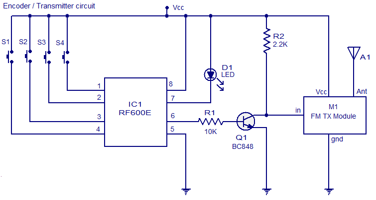
Here is the circuit diagram of an FM remote encoder/decoder using the ICs RF600E and RF600D. These devices are designed to provide a high level of security and operates from anything between 2 to 6.6V DC. Various electronic circuits like remote control systems, remote alarm systems, anti theft alarms etc can be implemented using the RF600E/RF600D pair.
The remote systems given here uses FM for the transmission. IC1 RF600E and its associated components form the encoder circuit. Pins 1 to 4 forms the switch inputs of IC1. When each push button switch is pressed a corresponding code will be generated at the pin 6 which is the data output pin. The encoded signal available at pin 6 is buffered using the transistor Q1 and the fed to the input of a general purpose FM transmitter module (M1). Such FM transmitter modules are very common in the market now.
The decoder system comprises of the IC2 RF600D and its associated components. Pins 17, 18, 1 and 2 are the digital data output pins of RF600D corresponding to the input switches S1 to S4 of the encoder/transmitter circuits. The digital data output pins 17,18,1 and 2 are asserted low when the relevant inputs S1 to S4 on the IC2 RF600E are asserted. M2 is a general purpose FM receiver module which receives the transmitted code and feds it to the data input (pin 9) of the IC2. Switch S1 can be used to select between latching and momentary digital output function. In latching mode digital output pins (OP1 to OP4) are only asserted for the corresponding transmit signal. In latching mode the output state is changed on each corresponding transmit signal. The learn switch S5 is used to enter the decoder IC in to the “learn mode”. Learn operation using push button switch S5 is as follows. 1) Press and release the push button switch S5. 2) The status LED D2 will glow when S5 is pressed and will remain ON when S5 is released. 3) Operate the encoder/transmitter once. 4) The status LED D2 will become OFF. 5) Operate the encoder/transmitter again. 6) The status LED will start flashing. 7) When the flashing of status LED stops, the encoder will be successfully taught to the decoder and the transmitter/encoder will now operate the receiver/decoder system. Up to seven encoder/transmitters can be learnt to each RF600D.Pin 3 of IC2 is the transmitter low battery indicator output and pin 11 is the serial data output.

 Circuit diagram.


Notes.
  • Assemble the circuit on a good quality PCB.
  • The ICs can be operated from anything between 2V to 6.6V.
  • Switches S1 to S5 are miniature push button switches.
  • S6 can be a miniature two way switch.
  • Transmit LED D1 will glow whenever the encoder is transmitting.
  • The power supply must be properly regulated and ripple free.
  • I recommend using batteries for powering the circuit.
  • Go through the datasheets of RF600E and RF600D before attempting this circuit.
 Source  http://www.circuitstoday.com
0 comments

5 channel radio remote control

TX-2B / RX / 2B  5 channel radio remote control.

This article is about a simple 5 channel radio remote control circuit based on ICs TX-2B and RX-2B from Silan Semiconductors. TX-2B / RX-2B is a remote encoder decoder pair that can be used for remote control applications. TX-2B / RX-2B has five channels, wide operating voltage range (from 1.5V to 5V), low stand by current (around 10uA), low operating current (2mA), auto power off function and requires few external components. The TX-2B / RX-2B was originally designed for remote toy car applications, but they can be used for any kind of remote switching application.

Circuit diagrams and description.

Remote encoder / transmitter circuit.

Click on image and zoom

 5 channel redio remote control encoder / transmitter circuit

The TX-2B forms the main part of the circuit. Push button switches S1 to S5 are used for activating (ON/OFF) the corresponding O/P channels in the receiver / decoder circuit. These push button switches are interfaced to the built-in latch circuitry of the TX-2B. Resistor R7 sets the frequency of the TX-2B’s internal oscillator. Resistor R1 and Zener diode D1 forms a simple Zener regulator circuit for providing the IC with 3V from the 9V main supply. C2 is the filter capacitor while C1 is a noise by-pass capacitor. D2 is the power on indicator LED while R6 limits the current through the same LED. S1 is the ON/OFF switch. The encoded control signal will be available at pin 8 of the IC. The encoded signal available at pin 8 is without carrier frequency. This signal is fed to the next stage of the circuit which is a radio transmitter. Crystal X1 sets the oscillator frequency of the transmitter section. R2 is the biasing resistor for Q1 while R3 limits the collector current of Q1. The encoded signal is coupled to the collector of Q1 through C3 for modulation. Transistor Q2 and associated components provide further amplification to the modulated signal.

Remote receiver / decoder circuit.
Click on image and zoom
 5 channel radio remote decoder

The remote receiver circuit is built around the IC RX-2B. The first part of the circuit is a radio receiver built around transistor Q1. The received signal is demodulated and fed to pin 14 of the IC. Pin 14 is the input of the built in inverter inside the IC. R2 sets the frequency of the IC’s internal oscillator. O/P 1 to O/5 are the output pins that are activated corresponding to the push buttons S1 to S5. Zener diode D1 and resistor R12 forms an elementary Zener regulator for supplying the RX-2B with 3V from the 9V main supply. C12 is the filter capacitor while R11 is the current limiter for the radio receiver section. Diode D2 protects the circuit from accidental polarity reversals. C15 is another filter capacitor and C14 is a noise by-pass capacitor.

Notes.

  • This circuit can be assembled on a vero board or a PCB.
  • Use 9V DC for powering the transmitter / receiver circuits.
  • Battery is the better option for powering the transmitter / receiver circuit.
  • If you are using a DC power supply circuit, it must be well regulated and free from any sort of noise.
  • Both ICs must be mounted on holders.

Interfacing relay to the RX-2B output.

The method for interfacing a relay to the output of RX-2B is shown below. When push button switch S1 of the transmitter circuit is pressed, pin O/P1 (pin 7 of the RX-2B) goes high. This makes the transistor 2N2222 to conduct and the relay is activated. The same technique can be applied to other output pins of the RX-2B. The relay used here is a 200 ohm type and at 9V supply voltage the load current will be 45mA which is fine for 2N2222 whose maximum possible collector current is 900mA. When using relays of other ratings this point has to be remembered and do not use a relay that consumes a current more than the maximum possible collector current of the driver transistor.
 Interfacing relay to the remote decoder
2 comments
 
Support : Creating Website | Johny Template | Mas Template
Copyright © 2011. The Circuit - All Rights Reserved
Template Created by Creating Website Published by Mas Template
Proudly powered by Blogger