Featured Post Today
print this page
Latest Post
Showing posts with label Sensor. Show all posts

Dark Activated Terrace Lamp Circuit

Description
This device allows one or more lamps to illuminate at sunset and turn off at dawn.Q1 and Q2 form a trigger device for the SCR, providing short pulses at 100Hz frequency. Pulse duration is set by R2 and C1.When the light hits R1, the photo resistor assumes a very low resistance value, almost shorting C1 and preventing circuit operation. When R1 is in the dark, its resistance value becomes very high thus enabling circuit operation. 
Circuit Diagram:

Parts
  • R1 = LDR
  • R2 = 100K
  • R3 = 200K
  • R4 = 470R
  • R5 = 12K
  • R6 = 1K
  • R7 = 470R
  • C1 = 10nF-63V
  • D1 = TIC106D
  • D2 = 1N4007
  • D3 = 1N4007
  • D4 = 1N4007
  • D5 = 1N4007
  • Q1 = BD327
  • Q2 = BD337
  • SK1 = Female Mains Socket 
 Notes:
  • R3 allows fine setting of operating threshold and R2 value can be raised to 150K maximum.
  • Several lamps wired in parallel can be connected to the circuit, provided total power dissipation of the load does not exceed about 300 - 500W.
  • PL1 can be omitted and the input mains supply wires connected in parallel to any switch controlling lamps. In this case, if the switch is left open, the circuit will be able to drive the lamps; if the switch is closed, the lamps will illuminate and the circuit will be by-passed.
  • Warning! The circuit is connected to 230Vac mains, and then some parts in the circuit board are subjected to lethal potential! Avoid touching the circuit when plugged and enclose it in a plastic box. 
Source -  http://www.extremecircuits.net/2009/06/dark-activated-terrace-lamp_19.html
0 comments

Water Pump Relay Controller Circuit Schematic

Description
By means of a Relay, employed to drive a water pump, this circuit provides automatic level control of a water reservoir or well. The shorter steel rod is the "water high" sensor, whereas the longer is the "water low" sensor. When the water level is below both sensors, IC1C output (pin #10) is low; if the water becomes in contact with the longer sensor the output remains low until the shorter sensor is reached. At this point IC1C output goes high, Q1 conducts, the Relay is energized and the pump starts operating.
Now, the water level begins to decrease and the shorter sensor will be no longer in contact with the water, but IC1C output will be hold high by the signal return to pin #5 of IC1B, so the pump will continue its operation. But when the water level falls below the longer sensor, IC1C output goes low and the pump will stop. SW1 is optional and was added to provide reverse operation. Switching SW1 in order to connect R3 to pin #11 of IC1D, the pump will operate when the reservoir is nearly empty and will stop when the reservoir is full. In this case, the pump will be used to fill the reservoir and not to empty it as in the default operating mode.
Circuit Diagram:
Parts:
  • R1 = 15K - 1/4W Resistors
  • R2 = 15K - 1/4W Resistors
  • R3 = 10K - 1/4W Resistor
  • R4 = 1K - 1/4W Resistor
  • D1 = LED - any type and color
  • D2 = 1N4148 - 75V 150mA Diode
  • Q1 = BC337 - 45V 800mA NPN Transistor
  • IC1 = 4001 Quad 2 Input NOR Gate CMos IC
  • SW = SPDT Toggle or Slide Switch (Optional)
  • RL1 = Relay with SPDT 2A @ 230V switch
  • Coil Voltage 12V - Coil resistance 200-300 Ohm
  • Two steel rods of appropriate length 
Notes
  • The two steel rods must be supported by a small insulated (wooden or plastic) board.
  • The circuit can be used also with non-metal tanks, provided a third steel rod having about the same height of the tank will be added and connected to the circuit's negative ground. 
 Source http://www.extremecircuits.net/2010/01/water-pump-relay-controller-circuit.html
0 comments

On Off Touch Switch Circuit

Description 
 The modern mechanic switches are improved concerning of old technology. We need however many times to replacement some old switch or to check currents bigger than the durability of certain switches or simple we need something with modern appearance. For he and different reasons is essential the up circuit. It is simple in the manufacture and the materials that use they exist everywhere. 
Circuit Diagram:
Parts:
  • R1 = 3.3M
  • R2 = 3.3M
  • R3 = 10K
  • R4 = 1K
  • C1 = 10nF-63V
  • D1 = 1N4007
  • D2 = Red LED
  • Q1 = BC547
  • IC1 = NE555
  • RL1 = 12V Relay
Circuit Operation:
 This circuit is based on the well known timer IC 555 (IC1), which drives a relay of which the contacts play the role of switch. The metal surfaces can have what form we want, but it should they are clean and near in the circuit. In order to it changes situation it suffices touch soft somebody from the two plates. Plate MP1 in order to the contacts of RL1 close [ON], or plate MP2 in order to the contacts of RL1 open [OFF]. The current that RL1 will check depended from his contacts. The Led D2 turns on when the switch they are in place ON and the contacts of RL1 closed. Two small pieces of metal can be used instead of MP1 – MP2. Because MP = Metal Plate.


Source http://www.extremecircuits.net/2009/08/on-off-touch-switch-circuit.html
0 comments

Capacitive Sensor Circuit Schematic Diagram

Special design for shop-windows animation
Useful for many types of touch controls
Circuit diagram:
Parts:

R1,R2_____1M  1/4W Resistors
R3,R4____47K  1/4W Resistors

C1_______10µF  25V Electrolytic Capacitor
C2______470pF 630V Ceramic or Polyester Capacitor

D1-D3____1N4002 100V 1A Diodes

Q1-Q3_____BC337  45V 800mA NPN Transistors

RL1_______Relay with SPDT 2A @ 220V switch
          Coil Voltage 12V. Coil resistance 200-300 Ohm

J1________Two ways output socket

Sensor____Aluminium or copper thin sheet with the dimensions of a post-card,
          glued at the rear of the same (about 15x10.5 cm.)

Thin screened cable
Circuit Description: 
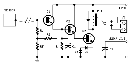
The purpose of this circuit is to animate shop-windows by means of a capacitive sensor placed behind a post-card-like banner. The card is placed against the glass inside the shop-window, and the visitor can activate the relay placing his hand on the card, from the outside. Especially suited for toy-shops, the circuit can activate model trains, small electric racing cars, lights etc. Further applications are left at user's imagination. Adopt it to increase the impact of your shop-window on next Christmas season!
Q1, Q2 & Q3 form a high impedance super-Darlington that drives the relay, amplifying the 50 or 60Hz alternate mains-supply frequency induced in the sensor by the human body. C1, D2 & D3 ensure a clean switching of the relay. Power supply can be any commercial wall plug-in transformer adapter with rectifier and smoothing capacitor, capable of supplying the voltage and current necessary to power the relay you intend to use.
Note: 
  • For proper operation, circuit ground must be connected via a small value, high voltage-rating capacitor to one side of the mains supply socket. The "Live" side is the right one.
Source - http://redcircuits.com/Page22.htm

0 comments

Electromagnetic Field Detector Circuit

Circuit diagram 
This lovely circuit is a real gem! Easy to assemble and more sensitive than many commercial devices available. It's based around an LF351 low-noise operational amplifier and a 1mF choke acting as the sensor. Unlike most other simple EMF detectors, this one has a meter output for accurate reading, but alternatively, you can also roughly estimate the frequency of the field by plugging in headphones. It can detect any field from 50Hz to 100kHz, making it highly versatile and a worthwhile addition to any hobbyist's workbench.
Problems:
 I just couldn't find any.
Possible uses:
 Find out how far electromagnetic fields extend in your room, house, office...
Are you a ghost hunter? Then this is the circuit that you've been waiting for! Since it has been observed that appearance of a ghost tends to disturb the EMF, you can now detect any such changes with this little detector.

Author: Andy Collins' Circuit Exchange
Source - http://www.zen22142.zen.co.uk/
1 comments
 
Support : Creating Website | Johny Template | Mas Template
Copyright © 2011. The Circuit - All Rights Reserved
Template Created by Creating Website Published by Mas Template
Proudly powered by Blogger