Featured Post Today
print this page
Latest Post
Showing posts with label Test and measurement. Show all posts

Simple Logic Probe Circuit

Description 
This simple logic probe has both LEDs on with no signal at the input but due to the nor gates connected to the probe, indicates correctly when a high or low signal is present. It also works correctly for pulse trains. Normally both LEDs are forward biased and therefore on, powered by the 12V supply. When a logic "high" is present at the probe, IC1a's output goes low sending IC1b's output high. This turns off LED1 but forward-biases (and turns on) LED2. Conversely, a logic "low" at the probe will send IC1b low, turning LED1 on and LED2 off. 
Circuit Diagram:
Source http://www.extremecircuits.net/2010/05/simple-logic-probe.html
0 comments

Electronic Stethoscope Circuit

Circuit Diagram
Description:
U1a operates as a low-noise microphone preamp. Its gain is only about 3.9 because the high output impedance of the drain of the FET inside the electret microphone causes U1a’s effective input resistor to be about 12.2K. C2 has a fairly high value in order to pass very low frequency (about 20 to 30Hz) heartbeat sounds.
U1b operates as a low-noise Sallen and Key, Butterworth low-pass-filter with a cutoff frequency of about 103Hz. R7 and R8 provide a gain of about 1.6 and allow the use of equal values for C3 and C4 but still producing a sharp Butterworth response. The rolloff rate is 12dB/octave. C3 and C4 can be reduced to 4.7nF to increase the cutoff frequency to 1KHz to hear respiratory or mechanical (automobile engine) sounds.
The U4 circuit is optional and has a gain of 71 to drive the bi-colour LED.
U5 is a 1/4W power amplifier IC with built-in biasing and inputs that are referred to ground. It has a gain of 20. It can drive any type of headphones including low impedance (8 ohms) ones.
Parts
R1 10K 1/4W Resistor
R2 2.2K 1/4W Resistor
R3, R9 Not used
R4 47K 1/4W Resistor
R5, R6, R7 33K 1/4W Resistor
R8 56K 1/4W Resistor
R10 4.7K 1/4W Resistor
R11 2.2K to 10K audio-taper (logarithmic) volume control
R12 330K 1/4W Resistor
R13, R15, R16 1K 1/4W Resistor
R14 3.9 Ohm 1/4W Resistor
C1, C8 470uF/16V Electrolytic Capacitor
C2 4.7uF/16V Electrolytic Capacitor
C3, C4 0.047uF/50V Metalized plastic-film Capacitor
C5 0.1uF/50V Ceramic disc Capacitor
C6, C7 1000uF/16V Electrolytic Capacitor
U1 TL072 Low-noise, dual opamp
U2, U3 Not used
U4 741 opamp
U5 LM386 1/4W power amp
MIC Two-wire Electret Microphone
J1 1/8" Stereo Headphones Jack
LED Red/green 2-wire LED
Batt1, Batt2 9V Alkaline Battery
SW 2-pole, single throw Power Switch
Misc. Stethoscope head or jar lid, Rubber Sleeve for microphone.
Assembly:
1) Assemble the circuit using Veroboard (stripboard) or a PCB.
2) Use a shielded cable for the microphone as shown on the schematic.
3) Fasten the microphone to the stethoscope head with a rubber isolating sleeve or use a short piece of rubber tubing on its nipple. A thick jar lid can be used as a stethoscope head. The microphone must be spaced away from the skin but the stethoscope head must be pressed to the skin, sealing the microphone from background noises and avoiding acoustical feedback with your headphones.
4) The microphone/stethoscope head must not be moved while listening to heartbeats to avoid friction noises.
5) Protect your hearing. Keep the microphone away from your headphones to avoid acoustical feedback.
Author: Audioguru
e-mail:
Source: http://www.electronics-lab.com/
1 comments

Pulse-Generator & Signal-Tracer Circuit Diagram

Dual-purpose test-instrument
Very simple circuitry, 1.5V Battery-operated
Circuit Diagram 
Parts:
  • R1 1M 1/4W Resistor
  • R2,R4 2K7 1/4W Resistors
  • R3 150K 1/4W Resistor
  • C1 2n2 630V Ceramic or Polyester Capacitor (See Notes)
  • C2,C3 4n7 63V Ceramic or Polyester Capacitors
  • D1 1N4148 75V 150mA Diode
  • Q1 BC547 45V 100mA NPN Transistor
  • Q2 BC557 45V 100mA PNP Transistor
  • SW1 SPST miniature Slider Switch (See Notes)
  • J1 Stereo switched 3mm. Jack socket (See Notes)
  • Probe Metal Probe 3 to 5 cm. long
  • Clip Miniature Crocodile Clip
  • B1 1.5V Battery (AA or AAA cell etc.) 
Device Purpose:
This simple circuit generates narrow pulses at about 700-800Hz frequency. The pulses, containing harmonics up to the MHz region, can be injected into audio or radio-frequency stages of amplifiers, receivers and the like for testing purposes. A high-pitched tone can be heard from the speaker of the device under test when all is working properly. The clip must be connected to the ground of the device under test, touching with the probe the different stages of the circuit, starting from the last stage and going up towards the first. When the tone is no longer heard, the defective stage has been found.
Connecting an earclip or headphone to J1, the circuit will automatically change into a two-stage amplifier and any audio signal coming from the device under test and picked-up by the probe will be heard through the headphones. The testing of a circuit should be made in the reverse manner, i.e. starting from the first stage and going down until the last stage. When nothing is heard, the defective stage has been found.
Circuit Operation: 
 Q1 & Q2 form a complementary astable multivibrator, whose operating frequency is set mainly by R3, C2 & C3 values. Output pulses are taken at Q2 Collector and applied to the probe by means of decoupling capacitor C1. D1 provides a symmetrical shape for the output waveform. If an earclip or headphone jack is plugged into J1, the connection from Q2 Collector and C1-C2 is broken by the switch incorporated into J1: in this case the circuit becomes a two-stage amplifier.

Notes:

  • If you intend to use the circuit to test valve operated devices C1 must be a 630V type. Working with low voltage supply transistor devices the voltage of C1 can be lowered to 63 or 100V.
  • If instead of a short probe, you intend to connect the circuit to the device under test by means of a piece of wire longer than a few centimeters, a small ceramic capacitor (470 to 1000pF) should be added in parallel to D1 to prevent unwanted RF oscillation.
  • Current drawing when in Pulse-Generator mode is about 60µA and 1.2mA when in Signal-Tracer mode operation. Therefore SW1 can be omitted, provided that the earclip or headphones are unplugged when the circuit is unused.
  • J1 is a stereo switched jack socket wired to obtain a series connection of the two earpieces forming a stereo headphone. In this manner the circuit is loaded with a higher impedance and sensitivity will be improved.
  • Therefore, the higher the load impedance the more sensitive the Signal-Tracer. In any case, common 32 Ohm impedance mini-headphones suitable for walkman sets will work fine.
  • A crystal (high impedance) earpiece is a good solution, provided you substitute J1 with a mono switched jack socket.
  • The entire circuit can be easily fitted into a pen-like enclosure, with the probe protruding like a nib. 

Author: RED Free Circuit Designs
Source http://www.redcircuits.com/
0 comments

Electronic Torricelli Barometer Circuit

Circuit Diagram 

Description
Although it does not have the same charm as real mercury barometers with long glass tubes on pieces of carved and polished wood, the Torricelli barometer discussed here is a functional equivalent and electronic replica of the Torricelli barometer. Actually, rather than displaying the atmospheric pressure on the traditional digital displays, we preferred to reproduce the general look of this respected predecessor of electronic barometers.
The mercury tube is, of course, replaced by a simple LED scale which, if not as beautiful, is still less toxic for the environment in case of breakage. As indicated on the drawing, the pressure sensor utilized is a Motorola MPX2200AP. This circuit is adapted for measuring absolute pressure and has a range well suited for atmospheric pressure. Without entering too deep into the technical details, such sensors deliver an output of voltage proportional not only to the measured pressure but, unfortunately, to their supply voltage as well.
Hence they must be powered from a stable voltage which is ensured here by the use of IC1. Since the output of the MPX2200 is differential and at a very low level, we had to resort to the use of four operational amplifiers IC4.A to IC4.D, contained in one LM324, to obtain levels that can be processed easily. As long as potentiometer P1 is adjusted correctly, this group of operational amplifiers delivers a voltage of 1 volt per atmospheric pressure of 1,000 hPa to the LM3914.
Since the atmospheric pressure will be within the range 950 to 1040 hPa at sea level, we need to make an expanded-scale voltmeter with this LM3914 in order to better exploit the 10 LEDs that it can control. That is the role of resistors R7 and R8 which artificially raise the minimum voltage value the chip is capable of measuring. Consequently, we can ‘calibrate’ our LED scale with one LED per 10 hPa and thus benefit from a measurement range which extends from 950 hPa to 1040 hPa. In principle, you should not have a need to go beyond that in either direction.
The circuit may be conveniently powered from a 9-volt battery but only if used very occasionally. Since this is usually not the case for a barometer, we advise you to use a mains adaptor instead supplying approximately 9 volts. Calibration basically entails adjusting the potentiometer P1 to light the LED corresponding to the atmospheric pressure of your location at the time. Compare with an existing barometer or, even better, telephone the closest weather station. They will be happy to give you the information. After Evangelista Torricelli, 1608-1647, Italian physician who proved the existence of atmospheric pressure and invented the mercury barometer.

0 comments

Crystal Tester Circuit

Description
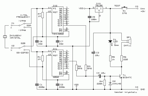
This circuit enables you to test quartz resonators at the range values from 32kHz to 24MHz. Confirmation of good state of quartz resonator is done by diode signalling LED and acoustic signal. Switch S2 enables change of range .
Circuit Diagram

Parts
  • R1,R7 1 M
  • R2,R3 5,6 k
  • R4 220 K
  • R5 1 k
  • R6 220
  • C1,C2 220 pF
  • C3,C4 10 F/25V RSM
  • C5 100 nF
  • C6,C7 33 pF
  • D1 LED 5 mm, yellow
  • D2 1N4148
  • T1 BC547C
  • IO1 4060
  • IO2 74HC4060
  • IO3 78L05
  • S1 push button (normally open)
  • S2 Two-positional switch 
Layout


Source -http://www.elektroda.pl/
0 comments
 
Support : Creating Website | Johny Template | Mas Template
Copyright © 2011. The Circuit - All Rights Reserved
Template Created by Creating Website Published by Mas Template
Proudly powered by Blogger